I have two identical toroid power transformers, 120V primary and 350V-0-350V secondary.
Can I wire the secondary of each transformer together in series to get 700V-0-700V ?
If I can, what should I be aware of ?
The voltage will be rectified with 2 damper diodes and the CT will be grounded.
Is there a better way to wire this up ?
Can I wire the secondary of each transformer together in series to get 700V-0-700V ?
If I can, what should I be aware of ?
The voltage will be rectified with 2 damper diodes and the CT will be grounded.
Is there a better way to wire this up ?
There was a discussion about this in an older thread, I'll try to look it up. Result was that using two separate transformers in a full-wave CT rectifier configuration might lead to transformer saturation and hum, as each transformer core will see secondary current flow in one direction only.
Bridge rectification would work, but means two more damper diodes and another heater circuit due to the elevated cathode potential.
Greetings,
Andreas
EDIT: Of course you could build two separate supplies and add them at the output, but the upper one would be floated by +350V. Doable but there might be safety issues if not implemented properly.
Is there any difference between the DOUBLE transformer configuration and ONE transformer with dual primary and dual secondary with the secondary wired in series and use the connected wires as CT ?
The physical difference is that the windings are on the same core in the second case, on two different cores in the first.
It seems this makes a difference, manp111. I didn't believe it either.
With two different transformers as shown in the schematic above, each secondary only conducts current during one half-cycle of the mains. This seems to lead to core saturation effects, as most people claim - also happens with half-wave rectification.
If you have one transformer, there is secondary current in both half-cycles, balancing the transformer load over the whole mains cycle.
Greetings,
Andreas
Last edited:
Don't thank me. ")
It's only a few weeks past that I argued there shouldn't be a difference, but some googling gives a lot of results and explanations. Of course the double transformer configuration works, but it will need serious derating to avoid saturation effects.
One solution would be paralleling the two transformers and then use bridge rectification. Simple with silicon, somewhat more complicated with vacuum diodes.
Andreas
If you need much less current than the transformer is specified for, you may build it according to your schematic above. If I remember correctly, the derating factor is somewhat around 0.6 for half-wave rectification (and also for your setup).
If you are familiar with high voltages and safety measures, just make a test rig and increase the secondary current until saturation occurs. Then decide if your desired current is safe.
Andreas
If you are familiar with high voltages and safety measures, just make a test rig and increase the secondary current until saturation occurs. Then decide if your desired current is safe.
Andreas
Don't thank me.
It's only a few weeks past that I argued there shouldn't be a difference, but some googling gives a lot of results and explanations. Of course the double transformer configuration works, but it will need serious derating to avoid saturation effects.
One solution would be paralleling the two transformers and then use bridge rectification. Simple with silicon, somewhat more complicated with vacuum diodes.
Andreas
Hi Andreas
Your gesture will magnify you !
Almost never, nobody in the forum, recognizes be human, and thus the possibility of being wrong.
You are an example and people like you improve our forum.
Best regards
Juan
Auf Deutsch gesagt Johann.
You will *definitely* lose power.
Not sure now whether you'll get 45% or 60% of rated current, but anyway it's a huge loss.
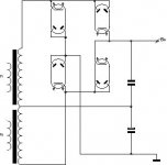
*Best* is to have each transforner end to end wiring rectified full wave with a bridge, which will give you around 1000V DC each with no VA loss, and then putting both DC supplies in series.
Having full VA rating and 2000V DC is *good*
Using tube rectifiers adds many constraints, besides requiring multiple very well insulated filament supplies, why bother?
Not sure now whether you'll get 45% or 60% of rated current, but anyway it's a huge loss.
*Best* is to have each transforner end to end wiring rectified full wave with a bridge, which will give you around 1000V DC each with no VA loss, and then putting both DC supplies in series.
Having full VA rating and 2000V DC is *good*
Using tube rectifiers adds many constraints, besides requiring multiple very well insulated filament supplies, why bother?
You will *definitely* lose power.
Not sure now whether you'll get 45% or 60% of rated current, but anyway it's a huge loss.
That's what I remembered, I think it was 60%, but I'll have to look it up..
Using tube rectifiers adds many constraints, besides requiring multiple very well insulated filament supplies, why bother?
Only because tube rectifiers exist and one likes to use one. There is no technical reason to prefer tube rectifiers. But there are reasons to like them - the looks, the warmth
and hey, they're tubes and that's what this part of the forum is about!Andreas
Using tube rectifiers adds many constraints, besides requiring multiple very well insulated filament supplies, why bother?
Tube rectifiers have built in soft start and delay
I do not know much about technical issues, but I do know that there are people who distinguish between the sound of valve and SS rectification.
I started using the EZ80-EZ81 in preamps, and 5R4GY-5U4GB in power amps, with MOSFET transistors, and low noise op amps, precision voltage references...
The result is wonderful, but difficult to describe in terms of sound, greater transparency is what comes to mind.
Valves have that "I do not know that"
But I can be wrong, as the guy who wanted to divorce his wife, the judge asks
- Why you married this woman?
--Because I saw her a "do not know that"
- Why now you want to divorce?
--Because I do not know that what saw her.
Last edited:
Take the two transformers and make a split supply?
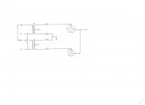
I think what an earlier poster meant by making two supplies and putting them in series was to make a "split" supply. That is, a positive and a negative supply.
A supply like that, using your two transformers as separate supplies would look something like this:
View attachment Split B-Plus Supply Experimental Power Supply Section.pdf
The B- rail becomes the reference for your amplifier - essentially it replaces the "ground". The advantage to doing this is that all of the power supply components including the transformer stay within their rated voltages relative to chassis - you don't have to worry about elevated voltage on the transformers, for example.
An example of a PA section might be something like this:
View attachment Split B-Plus Supply Experimental Amplifier Section.pdf
It would be an interesting exercise, this has been done many times before but we usually go in favor of simpler power supplies and spend most of the "lab" time on audio performance (like getting the dang hum out of the amp).
Based on your original question, then, it might be easier to bite the bullet and just order the transformer you really need.
Good luck!
I think what an earlier poster meant by making two supplies and putting them in series was to make a "split" supply. That is, a positive and a negative supply.
A supply like that, using your two transformers as separate supplies would look something like this:
View attachment Split B-Plus Supply Experimental Power Supply Section.pdf
The B- rail becomes the reference for your amplifier - essentially it replaces the "ground". The advantage to doing this is that all of the power supply components including the transformer stay within their rated voltages relative to chassis - you don't have to worry about elevated voltage on the transformers, for example.
An example of a PA section might be something like this:
View attachment Split B-Plus Supply Experimental Amplifier Section.pdf
It would be an interesting exercise, this has been done many times before but we usually go in favor of simpler power supplies and spend most of the "lab" time on audio performance (like getting the dang hum out of the amp
).Based on your original question, then, it might be easier to bite the bullet and just order the transformer you really need.
Good luck!
Last edited:
Tube rectifiers have built in soft start and delay
If it's all about soft start and delay, build a convenient, simple power supply with semiconductor diodes. Then choose a beefy tube rectifier with low forward voltage drop and just put in in series with the rectifier bridge!
Andreas
- Status
- This old topic is closed. If you want to reopen this topic, contact a moderator using the "Report Post" button.
- Home
- Amplifiers
- Tubes / Valves
- Power Transformer Wiring Question ?