Thanks very much to Ian and all who helped me with my first amp project. Thought I should report back that I have breadboarded one channel and am blown away by the clarity and quietness of this design.
I used a very simple CRC power supply (GZ34 - 50uf - 680R - 220uf) I threw in a large resistor value as I was only testing one channel and I was worried about too much voltage going around the circuit.
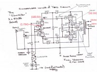
I have recorded my voltages and schematic in the attached jpeg. The only difference being that I omitted the 470R's and the 1k pot from the cathode section of the phase inverter. I have built the CCS and attached it directly to the cathodes. Could anyone tell me why the 470R and 1k pot was used in the original schematic?
I am tring to understand the phase inverter, i beleive it to be a long tailed pair?
I have read up lots on this but would love some clarification on my understanding. Am I right in thinking that electrons exist across the two cathodes which are joined together. If the signal presented on the grid is positive then it will encourage conductance towards its anode, however, if the grid signal is negative then it will repel electrons and they will subsequently be pulled to the anode of the other tube?
So why do we feed the cathodes with a CCS from a negative supply?
hmm, i bet i got it wrong but would love a mickey mouse explanation if anyone is willing to offer one?
Also, can anyone see any problems with the voltages I'm reading? will these drop significantly when I connect the other channel to the psu? I'm using a 270 - 0 -270V transformer that I pulled from an old heathkit s99 amp along with the OPT's
cheers Stuart
I used a very simple CRC power supply (GZ34 - 50uf - 680R - 220uf) I threw in a large resistor value as I was only testing one channel and I was worried about too much voltage going around the circuit.
I have recorded my voltages and schematic in the attached jpeg. The only difference being that I omitted the 470R's and the 1k pot from the cathode section of the phase inverter. I have built the CCS and attached it directly to the cathodes. Could anyone tell me why the 470R and 1k pot was used in the original schematic?
I am tring to understand the phase inverter, i beleive it to be a long tailed pair?
I have read up lots on this but would love some clarification on my understanding. Am I right in thinking that electrons exist across the two cathodes which are joined together. If the signal presented on the grid is positive then it will encourage conductance towards its anode, however, if the grid signal is negative then it will repel electrons and they will subsequently be pulled to the anode of the other tube?
So why do we feed the cathodes with a CCS from a negative supply?
hmm, i bet i got it wrong but would love a mickey mouse explanation if anyone is willing to offer one?
Also, can anyone see any problems with the voltages I'm reading? will these drop significantly when I connect the other channel to the psu? I'm using a 270 - 0 -270V transformer that I pulled from an old heathkit s99 amp along with the OPT's
cheers Stuart
Attachments
Stuart,
Just spotted your thread.
The sound quality of this amp is at absolute best when both the triode sections and the pentode sections of the ECL86 (6GW8) are matched. To get an ideally matched pair of tubes you may have to test dozens of tubes assuming that you actually have that many.
The pot in the cathodes of the diff amp with the wiper to the CCS allows you to balance the operation of the diff amp. What you are doing as you turn the pot from one end to the other is effectively adding resistance into one side or the other. The added resistance in the cathode of a triode provides negative feedback which "degenerates" the tubes gm. By adjusting the pot we add more resistance to one side and less to the other until the triode sections are effectively matched. I found that 1k pots were too big - resulting in throwing away too much gm, 100 Ohm pots usually did'nt have enough adjustment to trim the diff amp for exact balance and I did not have any 200 Ohm pots in my parts bin, so I used a 1K pot and reduced its effective value to approx a 300 Ohm pot by dropping a 470 Ohm from the wiper to each end. AS you have found, balancing the diff amp exactly is not required for to get good performance, it just helps a little for exceptional performance.
The other thing about the diff amp balance is that any imbalance introduces even harmonic distortion ONLY and mostly 2nd harmonic at that. So it sounds euphonic and not objectionable.
The negative supply is required because the Constant current Source (CCS) needs a certain amount of "Compliance" Voltage. That is the amount of voltage that will be across the CCS when it is operating at its set current, in this case that is about 3 to 4 volts which means that the bottom of the CCS has to be 4V less than the cathode voltage, the cathode voltage will not be a steady DC level, in any diff amp it will have 1/2 of the input signal AC voltage on it to so it is safest to say we need the supply at 4V or more below 0V rather than 4 V or more below the cathode.The easiest way to get a suitable supply in the amp I built was to rectify and filter a heater winding which gave around 7 volts. It can be much more up to the voltage limit of the transistors used.
That phase splitter is just a differential amp. The CCS in the common cathode connection guarantees that the total current through the two triodes is always constant. As one conducts more current (more voltage drop across the anode load) it's anode swings lower and the other triode MUST conduct less current (less voltage drop across it's load resistor) and it 's anode swings higher. So as you apply signal to the input triode it swings current which follows the input signal and the triode on the other side of the diff amp swings current opposite phase to the input signal. You can actually see this at work. As the "non-input" triode has its grid tired to 0V and the drive signal for a triode is the grid to cathode voltage you will find that the common cathodes will have 1/2 the input AC voltage on them.
The unit I built is now with one of my sisters, powering a set of Polk Audio Monitors and driven from a Vintage Marantz preamp. This amp was the prototype or concept demonstartor for the Baby Huey design.
Hope this answers your questions. Tried to keep it accurate without too much theory.
Never been one of the "If you can't blind them with science then baffle them with B.S." school.
Cheers,
Ian
Last edited:
Thanks for taking the time to explain Ian... the amp sounds great - however it seems to saturate into an awful crunching noise if the volume is turned more than half way. I'm feeding the 3ohm output into a 10inch tannoy monitor gold speaker.i think the volume is acceptable so I may just live with it, although i did wonder if i had done something wrong.
Would it be possible that without the resistance in the cathodes which would yield less gm, could i be feeding the pentodes with too much signal?
I measured 1.73 V at the cathode pair.
Another question I had, sorry to be a pain, was that I noticed that the el84 huey uses bias in the pentode section, would this make a huge difference in the ecl86 design?
And finally... I have omitted to use the global negative feedback so far, would it be worth introducing this, could it be the cause of distortion at higher volumes? And would I simply connect the global neg feedback from the 15ohm winding of the OPT even though i connect speakers to 3ohm?
Aprreciating the help!
Stuart
The measurement of 1.73 volts at the cathodes give me confidence that this section including the constant current source is working correctly.
You do have bias in the Pentode section, it is auto bias (usually called cathode bias) from those 390 Ohm resistors in the Pentode cathodes, that voltage of 12.1 V you marked on the schematic tells be that that is working correctly too. The Baby Huey's used a different form of bias.
It should be fine without global feedback. Adding it would reduce the sensitivity which means it would go into that "awful crunching noise" saturation at a higher volume pot setting but not an actual higher volume.
It is a bit hard to judge if that is indicating you have a problem or not but I think probably not. You have to remember that this is an 7 or 8 Watt Amp. Auto (Cathode) biased amps tend to do this when you overdrive them.
On the feedback - I tend to adjust that 15K cross connect resistor which sets the local feedback level first - too high a value (too much feedback) and you loose stereo imaging, pace and attack. too low and it becomes "over bright" and the bottom end becomes loose and wooly. Onc e i have that set to my liking then if necessary to tame bottom end woolyness I add global feedback.
The values on the schematic you used (15K local feedback and no global) are what worked on my amp driving the Polk Audio Monitors. Don't get too hung up on tuning fore-ever, on the last Baby Huey build I spent weeks adjusting that local feedback resistor, what was perfect on one music selection was only 90% on another music selection, probably nor surprising that in the end what was best was right in the middle of the highest and lowest values based upon tuning for every new CD I played.
If you add global feedback that can be "sourced" from any tap on the secondary of the output tranny, the series resistor value needs to change depending upon which tap you use.
8 Ohm tap has 1.4 x the voltage of the 4 Ohm tap and the 16 Ohm tap has 2 x the voltage of the 4 ohm tap and 1.4 x the voltage of the 8 Ohm tap. The resistor value needs to be scaled in direct proportion to the voltage.
Cheers,
Ian
Thanks very much Ian, am slowly learning thanks....
Have gone out and purchased a couple of 220R mini pots. I will connect the wiper to the CCS supply and each cathode of the diff amp to the other connections. Would like to know how to make the adjustment, I presume it is not just done by ear? I do not have an oscilloscope but i do have a humble digital voltmeter. Can i make the balance with the multimeter and if so how?
cheers in advance!
Stuart
Think I may have worked it out... should I be adjusting the ccs pot so that I have equal voltages at both anode sections of the triode? Am assuming I can just use one multimeter to go back and forth between anodes until it is balanced?
Have kept the 15K resistor and will try not to get obsessed with changing the value for every track I listen to! Thanks for the advice, I can totally relate....
Have kept the 15K resistor and will try not to get obsessed with changing the value for every track I listen to! Thanks for the advice, I can totally relate....
Stuart,
Yes adjust for equal voltages at the 2 anodes. I've actually found you can get it pretty close just adjusting "by ear". If you are careful you can measure anode to anode and adjust for zero volts difference. From a practical stand point it is probably safer to connect one multimeter lead to 0V with a clip and then move the other probe from one anode to the other and adjusting for the same voltage. I have special clip on leads for my multimeter which I put on before applying power to the amp.
Of-course I can spend a bit more on fancy leads and stuff as I claim it on my tax return against my income from the Electronic Engineer day job.
Cheers,
Ian
Thanks Ian,
I haven't abandoned the amp or this forum - just been hard at work with the soldering iron!
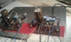
Have taken pics of this project and will hopefully do a write up, all credit to you of course for the original schematic and the help
Not sure if anyone else will have embarked on similar madness when it came to fitting components around the valve sockets
Stuart
I haven't abandoned the amp or this forum - just been hard at work with the soldering iron!
Have taken pics of this project and will hopefully do a write up, all credit to you of course for the original schematic and the help
Not sure if anyone else will have embarked on similar madness when it came to fitting components around the valve sockets
Stuart
Attachments
- Status
- This old topic is closed. If you want to reopen this topic, contact a moderator using the "Report Post" button.
- Home
- Amplifiers
- Tubes / Valves
- Gingertubes ecl86 amp build