Hi out there.
Recently i was offered some NOS RCA 829B tubes. It is a dual beam pover tube. Data comparable to kt88. I searched the net for some posible audio use and found that Cayin uses the tube in som rather nice looking amps. http://www.cayin.com/ (check the cayin 800MK) Has anny of you used this tube? I was thinking of building an pp triode amp inspired of the PP-1 amp http://www.vacuumstate.com/images/PP-1C_a.gif Anny coments on that. Anny advice is welcome.
Thanks Peter Jensen
webercarbmann said:Recently i was offered some NOS RCA 829B tubes.
National Valve Museum 829B
It is possible, but tricky to get these transmitter tubes to work as audio (or at least i have been told many times), I just sold off at least a half-dozen of these, but have kept some 815s (same config as the 829s, but cuter looking -- short R2D2 looking tubes with top caps angled off at an angle so they look like antenna :^)
Transmitters often get used in A2 amps (which at this point in my learning curve i sorta understand).
Dennis in Perth, OZ has built a 2E26 PP amp. He knows a lot about these kind of tubes.
There is also a Japanese publication on building SE amps with transmitter tubes which is often quoted as a reference when the subject comes up. SE Amps by Transmitting Tubes by Kouichi Shishido. Available from EIFL.
I to am planning some amps based on Allen Wright's Forced Symmetry concept (EL34, EL84, EL95). And i'm sure Bernhard will chime in, he has heard one of Allen's mules and was quite impressed...
dave
Hi again
Thanks for your reply dave. What is the tricky part in using transmitter tudes for audio? I know that some transmitter tubes work with high voltages but that is not the case with the 829B
Data http://frank.nostalgiaair.org/sheets/049/8/829B.pdf Is there a way to simulate how the tube vill behave in triode mode based on the current data.
You mention Allen Wright's Forced Symmetry concept, do you have a link with some more information on that?
Thanks Peter Jensen
The problem you can run into with transmitter tubes is that they can ocsillate at RF frequencies . Using the most direct / shortest wiring possible while keeping the input and output of the tube well seperated will help. A very low power supply impedance at RF will help also (good power supply bypass caps as close to the tube as possible). I'd try it.
Originally posted by webercarbmann
... You mention Allen Wright's Forced Symmetry concept, do you have a link with some more information on that? ...
Please get in contact with Allen Wright himself and discuss your intentions with him. Just to be sure you get current, updated info concerning "forced symmetry" from him. As i know him, he'll be very informative and helpful concerning his power amp topology.
He is subscribed to this forum and should be accessible via the email button, otherwise search his website www.vacuumstate.com for an email link.
Hi Group,
I have manually graphed many, many tubes - seeking a large linear triode for SE use. (I cannot reconcile the asking price for 300Bs)
Although I have not looked at the 829, I am most impressed with the European equivalent, the QQV06-40. My initial interest was triggered by old Philips figures quoting 3% distortion figures in classB modulator use! I would anticipate the 829 may well be equally linear.
When paralleled as a triode the QQV06-40 exhibits a plate resistance around 1000ohm and a mu of 8. When supplied with 425v. a load of 3k5, and biased at -40v, the tube outputs nearly 11 watts at an H2 distortion figure of 5%. That's nice, and there's more with 500v. (The g2 limiting value of 250v doesn't appear nasty at all and the run-away characteristic when breathing hard as displayed by the KT88/TT21 family just doesn't arise)
Two EL34s paralleled as a single triode are similar - more current, a little more output, a little less drive, and more distortion.
I have no qualms using tubes for other than their designated task. If you are looking for a nice super-linear, grunty driver for your output I have found nothing comes near the 6KV8. This is a TV tube with a frame-grid output tetrode and a very nice linear driver triode (gm of 60) Connect the tetrode as a triode. Distortion way under 1.5% is typical over a huge output voltage swing.
regards,
Graeme
webercarbmann said:You mention Allen Wright's Forced Symmetry concept, do you have a link with some more information on that?
Forced Symmetry Seminar Pics
dave
Hello,
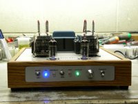
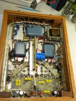
I am new to forums so If I make a mistake, I apologize in advance, As a retirement project I built a stereo 829B power amplifier in 2014, looks cool but needs some tweaking due to square wave overshoot, This is a Push Pull design and not totally conventional but I get approx. 25 watts per channel prior to clipping, I did use a balance on the bias for better matching but found the highest power output was from the JAN 829B, almost 30 watts prior to clipping, at 10 watt output the distortion is around .2% at 1khz. low frequencies suffer because of the output transformer, mostly at higher output levels, transformers are hand wound, that was a project. Upper frequencies are good and flat to 65Khz (needs compensation). It also needs more gain. I got better results with a 6BQ7A as input and phase inverter, originally I used a 6CG7. I have pictures and schematic if anyone is interested.
Karl
Attachments
Please post your schematic.
The circuit topology, the circuit values, and the output transformers are the primary possible causes of the square wave overshoot.
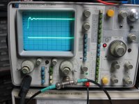
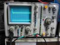
Please post a photo of the square wave and overshoot, including the time per division on the scope.
What is the rise time and fall time of your square wave signal generator?
What is the rise time and fall time of your amplifier when it is fed by the generator's square wave? (are you using a non-inductive load resistor for this test?)
The circuit topology, the circuit values, and the output transformers are the primary possible causes of the square wave overshoot.
Please post a photo of the square wave and overshoot, including the time per division on the scope.
What is the rise time and fall time of your square wave signal generator?
What is the rise time and fall time of your amplifier when it is fed by the generator's square wave? (are you using a non-inductive load resistor for this test?)
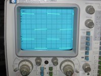
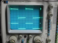
I put it on the bench this morning and there are some issues, It did not look like this 8 years ago so I need to see what failed, it was on my TV output for around 7 years and not played very loud but has lots of hours on it. I did try different tubes, same results. Yes, the load is non inductive, well at least under 1mHz. There is ringing at two freq's for top and bottom of square wave, both channels look the same, Top apx 65kHz (+) and bottom 150kHz (-). Maybe a phase shift problem due to bypass cap? It may be a week or so before I look at it.
The transformers are hand wound but lost pics in a computer crash, I interlaced windings pri and sec to minimize inter capacitance if that makes sense and had to build a counter for the turns, I remember 2350T + 2350T on the primary but that may be in error CT was calibrated by changing turns on the outer winding, The cores are from a destroyed juke box amplifier. I do have a pic of my first rewind of a burnt power TX maybe at a later time if interested.
The generator used is a HP 3325A and has very fast rise time, around .01us at 10% and 90%
There is a lot to talk about on this project, it is my second tube amplifier, first was a 8417 X 4ea when I was 18 years old and kind of scary, about 130 watts.
Pic's are labeled accordingly, I may have the board layouts but need to look
Karl
Attachments
From your schematic:
The input triode plate load resistor is only 1k Ohms?
10k Ohms, perhaps?
Quite a difference in the two types of input/ concertina driver tube:
The 6CG7 rp is 7700 Ohms, u = 20, Gm 2600 micro Mhos. Less gain.
The 6BQ7A rp is 5900 Ohms, u = 38, Gm6400 micro Mhos. More gain.
Negative feedback requires the frequency response of the amplifier to drop off, before the phase shift causes positive feedback.
Between these two factors there might be ringing or instablity.
Perhaps there was no ringing with the 6CG7, but there now is ringing with the 6BQ7?
Probably nothing to do with the problem, but for better performance, especially at low frequencies:
Check the output stage quiescent current balance, replace the single 10 Ohm sense resistor with Two 10 Ohm sense resistors, one each directly from an individual cathode to ground.
Are the scope photos taken with the switch set for Negative Feedback?
If you have a Test CD with a 1kHz square wave, probably the only ringing you will see is the pre-ringing at 22.05kHz, and post-ringing at 22.05kHz caused by the digital filter of the CD player and the 44.1k sample/sec. Or, if your CD player only has analog filtering, there is only post ringing.
There are no fast rise waves out of the CD player, so there will be none of the very high frequency ringing you saw from the fast rise square wave generator.
If everything else on the amplifier checks out OK, I would not worry about the 65kHz and 150kHz ringing you get with a very fast rise generator.
You are not likely to see any of that ringing from a CD player, and certainly not from a phono cartridge.
Enjoy the music. Sleep well at night.
Last edited:
First, thank you for pointing out some facts. All tests were performed with the feedback on, there is about a 2db gain with it off but all waveforms are about the same. Unfortunately the cathodes are internally connected together, same with the screens in the 829B, this makes things a little more difficult. I can short the cathode resistor without to much bias issues just to see, I thought the resistance would make it more stable, slight feedback in the output stage?
Yes, there are a few mistakes in the schematic, the 1k is a default in Circuitmaker that I used for drawing it and I missed it (maybe a few times), the plate load on the first triode is 390k and the coupling to the phase inverter is 330k (parallel with the .2uf). I am second guessing the values I used on all coupling cap's.
I am puzzled on the high freq response because it changed on both channels, I remember I was impressed with the amplifier above 20Khz, I am not now but it still sounds great. With the feedback removed (off), it still sounds great at low volume but the bass gets muddy with the volume turned up. Also if I deliberately select the wrong output impedance It sounds, well, not good. I wonder if this tube is that touchy with load impedance.
Originally it was going to be a 832 amp.
I do not know how to calculate the amount of feedback or is it only 2db, speaker impedance as a function of frequency would explain the different tonal response but into a resistive load I cannot see any change. when I get time I will look at the phase inverter output without the output tubes installed.
I had a hard time coming up with the soft start and turn off using a "P" channel mosfet, everything was designed upside down or positive ground, not common for me. There is no pop or thump. The screen voltage is regulated within a few volts, not sure how much the B+ changes but I will look into this.
Most parts used were what I had on hand but high quality resistors were installed in the finished amp.
If I built another, I would design it much differently but I do like this amp. Friends are surprised on how good a tube amp sounds. Warm up time is around 30 seconds
I will post a corrected schematic when I find my original drawings.
My only reason for trying to get a wide bandwidth is I have a "solid state test" amplifier built in the early 80's using a LM301 input stage, BW is DC to 1Mhz and a very low output Z, it sounds better than anything I have but it's only 20 watts per channel, I will never do a DC responding amp again. it is connected to my workbench TV now.
K
Did you originally test the square wave response with a 6CG7?
Now you use a 6BQ7A.
There is quite a difference between the two.
Is your workbench in a high humidity area?
High resistance circuits are sometimes affected by humidity.
I was mistaken, I forgot that both sections of an 829B beam power tube has the cathodes connected together inside the glass envelope.
There is no way to use separate cathode resistors.
Unbalanced plate currents are not much of a problem for an RF amplifier that uses air core transformers.
Audio, with push pull output transformer laminations has a problem with unbalanced plate currents. You either have to measure the DCRs of the
individual plates to center tap, and then measure the voltage drop across those individual DCRs, or just insert a precision 10 Ohm resistor in each plate lead, and measure the voltage across the 10 Ohm resistors.
I use test point sockets that my meter lead tips plug into for safer measurements.
That way, you can balance the DC currents by adjusting the pot.
Last edited:
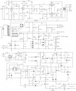
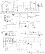
I corrected the schematic but made a few modifications also, I do not know how to replace schematic on past post so I will just add it here, I apologize for the errors.
Now for the bad news, the major problem is the output transformers, I get the best power and response into 8 ohms but I am confused on the plate to plate readings I see on some output TX's, shouldn't it be B+ to Plate, this makes sense to me but I am not an engineer, I believe I am in the ball park, there is about 1150 + 1150 Turns on the primary winding.
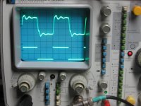
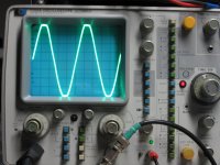
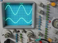
There is a 3db increase in power with the 6BQ7. I did add some capacence between the two output plates (470pf) and 1500 pf across the 4.7K feedback resistor and lowered the cathode resistor to 1.5 ohms, I am using the 6CG7 now. One good thing is when troubleshooting it is easy to sub another transformer with the plate leads on the top of the tube, I used a 100 watt guitar TX of unknown origin but the results were surprising, first more distortion, up to around 1.5% at 10 watts 1khz. Power was up to 30 watts at clipping and a 20khz square wave looks much better.
The phase inverter drives the grid to 0v at clipping, I thought this was odd. With power off I also applied a 10khz square wave to the primary of each Plate to B+ connection and I am dumbfounded how bad it looked, very different on each plate lead, one was a ringing square wave and the other a triangle shape waveform at the output. The output was loaded into 8 ohms and the generator output Z is 50 ohms, at the primary signal looked very good, the test TX looked good with a little ringing but was balanced between each plate and B+connection.
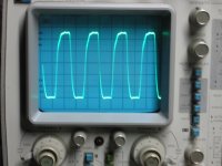
Below is the corrected schematic and the test TX at 20 khz @ 20 watt output, note bottom of waveform is not clipping.
I do not know what went wrong with the output TX, I wound a few Pri layers then a secondary layer and more pri layers and secondary layer for a total of 10 layers with heaver paper between Pri and Sec windings. I submerged in urethane varnish and applied a vacuumed to remove air out of the core, drained, and baked on the coal burner for a week....same process for the power TX with no issues, Yes, I have a device to count turns, would be impossible for me without it.
Any comments on TX winding, I know the core is to small for low bass frequencies at full power, 3 1/2"L X 2 3/4"W X 1 1/2" H
Now for the bad news, the major problem is the output transformers, I get the best power and response into 8 ohms but I am confused on the plate to plate readings I see on some output TX's, shouldn't it be B+ to Plate, this makes sense to me but I am not an engineer, I believe I am in the ball park, there is about 1150 + 1150 Turns on the primary winding.
There is a 3db increase in power with the 6BQ7. I did add some capacence between the two output plates (470pf) and 1500 pf across the 4.7K feedback resistor and lowered the cathode resistor to 1.5 ohms, I am using the 6CG7 now. One good thing is when troubleshooting it is easy to sub another transformer with the plate leads on the top of the tube, I used a 100 watt guitar TX of unknown origin but the results were surprising, first more distortion, up to around 1.5% at 10 watts 1khz. Power was up to 30 watts at clipping and a 20khz square wave looks much better.
The phase inverter drives the grid to 0v at clipping, I thought this was odd. With power off I also applied a 10khz square wave to the primary of each Plate to B+ connection and I am dumbfounded how bad it looked, very different on each plate lead, one was a ringing square wave and the other a triangle shape waveform at the output. The output was loaded into 8 ohms and the generator output Z is 50 ohms, at the primary signal looked very good, the test TX looked good with a little ringing but was balanced between each plate and B+connection.
Below is the corrected schematic and the test TX at 20 khz @ 20 watt output, note bottom of waveform is not clipping.
I do not know what went wrong with the output TX, I wound a few Pri layers then a secondary layer and more pri layers and secondary layer for a total of 10 layers with heaver paper between Pri and Sec windings. I submerged in urethane varnish and applied a vacuumed to remove air out of the core, drained, and baked on the coal burner for a week....same process for the power TX with no issues, Yes, I have a device to count turns, would be impossible for me without it.
Any comments on TX winding, I know the core is to small for low bass frequencies at full power, 3 1/2"L X 2 3/4"W X 1 1/2" H
Attachments
- Home
- Amplifiers
- Tubes / Valves
- 829B tubes for audio?