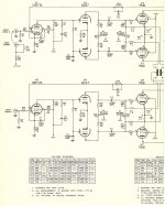
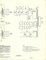
I was wanting to get something from my late friend Charles Kittleson's estate sale on the auction site; wound up with a Knight KB-85. Researching it I noted that many people were subbing 6L6 types for the rare EL-37s originally used. However the tube manuals indicate that the EL-37s were replaced by EL-34's. Sure enough the ratings are virtually identical. Triode electronics had the schematic; it is the classic 5-20 x 2; in fact there are 10 tubes on the amp. This is NOT your Stereo 70; the transformers are HUGE and it has dual rectifiers and a choke filtering the B+. Whoa the fuse was missing; but oh well lets stick a new one in and crank the Variac. 490 volts on the plates, and the bias was spot on the schematic values.
Plan is to re-cap it anyway; with snap-ons for the plate supply and a couple of PCBs mounting the smaller caps. Will run the stock circuit and get baseline measurements but that huge dual 5AR4 power supply is just begging me to run 6550s fixed bias from a low mu phase splitter.
Plan is to re-cap it anyway; with snap-ons for the plate supply and a couple of PCBs mounting the smaller caps. Will run the stock circuit and get baseline measurements but that huge dual 5AR4 power supply is just begging me to run 6550s fixed bias from a low mu phase splitter.
It sounds like you got your hands on a nice old amplifier. The best amplifier (subjectively) that I ever built used transformers from a Knight integrated amp. The transformers were huge and very high quality. The circuit was very modern even by today's standards, although I built it over 30 years ago. The amplifier that I scavenged worked fine when I gutted it, but the amplifier that I built worked a whole lot better.
The KB-85 schematic is also here. Yes, that setup strongly resembles the 5-20, down to an identical small signal complement.
The mention of big "iron" and a quick look at the EL37 data sheet has me thinking the 6550/KT88 idea may be good. Measure the end to end impedance of the O/P "iron" and post the number. If that # is approx. 3.2 KOhms, the big "beamie" looks real good. OTOH, if the # is approx. 4 KOhms, the EL34/6CA7/KT77 group may be best.
As it is obvious that corners were not cut in the KB-85, all sorts of options present themselves. IMO, perhaps the most interesting implementation of Mullard style topology is the H/K Cit. 5, with its emphasis on high gm small signal types. The supply of 12BY7s is dwindling. However, a 6922 in cascode will yield equivalent gm/gain and there's always the CCS in the LTP tail.
The mention of big "iron" and a quick look at the EL37 data sheet has me thinking the 6550/KT88 idea may be good. Measure the end to end impedance of the O/P "iron" and post the number. If that # is approx. 3.2 KOhms, the big "beamie" looks real good. OTOH, if the # is approx. 4 KOhms, the EL34/6CA7/KT77 group may be best.
As it is obvious that corners were not cut in the KB-85, all sorts of options present themselves. IMO, perhaps the most interesting implementation of Mullard style topology is the H/K Cit. 5, with its emphasis on high gm small signal types. The supply of 12BY7s is dwindling.
However, a 6922 in cascode will yield equivalent gm/gain and there's always the CCS in the LTP tail.Attachments
Last edited:
I have an H/K Cinco; in fact there was a screaming deal going down for another one at the same time as Charlie's amp; the Cinco went for less than $450 less than 2 minutes after I hit the bid button with less than 2 seconds to spare on the Knight. This Knight was a better deal; and it appears that it is even a runner and it has the tube cage. Charlie used to love having me bring my MI-200s to run his Maggies at his place; this amp is a fitting tribute.
The sovtek 5AR4's came in from Yen Audio; completing the tube complement of winged C EL34's; Amperex EF86's and American 12AX7's. On to the bench for some base line measurements. Power is about 40WPC; power BW goes down to 25 Hz and up to 20kHz. Damping is very high. There is a lot of tendency for the amp to break out in high frequency oscillations, at the higher power levels. I managed to tame that down by switching the phase inverters to 12AT7's. The above measurements are with the 12AT7's.
Russian 5AR4s are quite capable of delivering the rated 250 mA., but they can get into trouble at the top of the type's voltage range. The uploaded pictorial (not original to me) shows a very effective tweak. The only thing I would do differently is using UF4007s, as they generate FAR less switching noise than 1N4007s.
Attachments
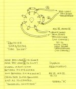
Hmm, I think Eli's suggestion simply improves the voltage handling of the 5AR4 by placing the solid state diodes in series with the rectifier plates. You will still get the identical slow-start that the tube diode provides.
Correct! The "sand" diodes provide some additional PIV headroom. PIV headroom is the area where Russian 5AR4s can come up short. Performance of the composite, both sonic and turn on, is COMPLETELY dominated by the vacuum rectifier.
My apologies I did not closely review the diagram. Actually the turn OFF is most dominated by the vacuum diode which must momentarily shoulder the entire load while the sand gets its act together. The SiC diodes since they are majority carrier devices do not have the transition noise of standard diodes. Actually that is a moot point though because the BEST thing to do is to run TV damper diodes. There is plenty of room in that huge chassis to add a filament transformer and the dampers are AMERICAN and inexpensive. I like 6AU4's.
My apologies I did not closely review the diagram. Actually the turn OFF is most dominated by the vacuum diode which must momentarily shoulder the entire load while the sand gets its act together. The SiC diodes since they are majority carrier devices do not have the transition noise of standard diodes. Actually that is a moot point though because the BEST thing to do is to run TV damper diodes. There is plenty of room in that huge chassis to add a filament transformer and the dampers are AMERICAN and inexpensive. I like 6AU4's.
All I can tell you is that the "fireworks" in current production 5AR4s stop, when the series "sand" diode tweak is employed. Look here. Todd's thought about the SS parts going Zener can't be discounted.
I agree that the 6AU4 is impressive.
On this amp since it is running 2 rectifiers going TV damper is a no-brainer. If I were to run the series diode thing I would have to determine how to do it since this is NOT your ST-70. I will let the Forum know what I decide to do and provide schematics when appropriate. Thanks all for the excellent tips and help. BTW my tests indicate that the amplifier front end and output stage circuitry are both in need of some serious tweaks as well, in order to let that excellent output iron 'breathe'.
I wound up running two UF4007's in series;took care of the problem. I also gutted that 700V 16uF cap and slid a couple of 47uF 350 v modern caps into the tube. Now the unit is running properly with a quad of Svetlana EL-34's in it. It clips smoothly at a tad under 50V P-P into 8-Ohms so that is around 30 watts.
Knight KB85
The tube manual that said the EL34 replaces the EL37 is dead wrong...The EL37 would be closer to a KT66 than an EL34...The current draw of the filament of a 6L6 is a half an amp less than the EL37 but all the other specs are very close Certainly not an EL34.
TDSL Tube data [EL37]
I was wanting to get something from my late friend Charles Kittleson's estate sale on the auction site; wound up with a Knight KB-85. Researching it I noted that many people were subbing 6L6 types for the rare EL-37s originally used. However the tube manuals indicate that the EL-37s were replaced by EL-34's. Sure enough the ratings are virtually identical. Triode electronics had the schematic; it is the classic 5-20 x 2; in fact there are 10 tubes on the amp. This is NOT your Stereo 70; the transformers are HUGE and it has dual rectifiers and a choke filtering the B+. Whoa the fuse was missing; but oh well lets stick a new one in and crank the Variac. 490 volts on the plates, and the bias was spot on the schematic values.
Plan is to re-cap it anyway; with snap-ons for the plate supply and a couple of PCBs mounting the smaller caps. Will run the stock circuit and get baseline measurements but that huge dual 5AR4 power supply is just begging me to run 6550s fixed bias from a low mu phase splitter.
The tube manual that said the EL34 replaces the EL37 is dead wrong...The EL37 would be closer to a KT66 than an EL34...The current draw of the filament of a 6L6 is a half an amp less than the EL37 but all the other specs are very close Certainly not an EL34.
TDSL Tube data [EL37]
Thanks for the input Mike. Look closer and you will note that the KT66/6L6GC requires a much smaller grid return resistor to operate properly. The EL34 on the other hand will operate using the same grid return resistors and the only thing one needs to do is a simple bias adjustment. I also have the Fisher AZ-80s and successfully swapped to EL34's. These Williamson amps are still nice and stable and happily put out 30 watts. Trying to sort out running the 6L6's would have been a nightmare; and another thing is that like the EL37's the EL34's are Power Pentodes as opposed to Beam Power Tubes.
Thanks for the input Mike. Look closer and you will note that the KT66/6L6GC requires a much smaller grid return resistor to operate properly. The EL34 on the other hand will operate using the same grid return resistors and the only thing one needs to do is a simple bias adjustment. I also have the Fisher AZ-80s and successfully swapped to EL34's. These Williamson amps are still nice and stable and happily put out 30 watts. Trying to sort out running the 6L6's would have been a nightmare; and another thing is that like the EL37's the EL34's are Power Pentodes as opposed to Beam Power Tubes.
Dave
The problem is that the EL34s draw more filament than the 6L6gc or EL37 and,the loading of 6.6k which the OPT are are typically too high for EL34s which run the neighborhood 5k at those voltages..I have several of these amps and the RCA 6L6gc black plates sound better than the EL37s believe it or not in these amps..The amps run very hot so the EL34 makes matters much worse as you will find out in these amps.
Last edited:
- Status
- This old topic is closed. If you want to reopen this topic, contact a moderator using the "Report Post" button.
- Home
- Amplifiers
- Tubes / Valves
- knight kb-85 restoration/mod