Just thought I'd bump this.
No hardware progress in the past 10 days as I fried my Arduino. I'm not sure what happened as it was running fine stepping the shaft and then there was a slight snap sound followed shortly thereafter by the 3 terminal regulator spewing its guts.
The USB interface chip went so no sense in trying to fix it. The regulator probably dumped 12VDC on the 5V circuitry. It was not on the computer USB port at the time so no damage to my main computer.
I just wonder if the stepper is somehow putting transients on the power supply that managed to get through the regulator and damage the board.
If so, I need to add some transient suppression.
I built a new 8V pre-regulator (7808 with heat sink) to drive the Arduino from the 20V supply. So hopefully there will not be a repeat of the event.
A new one arrived yesterday so I can get back to checking code, which is almost at Alpha.
Code is up to 900 lines of which about 330 lines are code.
Hardware has not progressed other than digging out a couple of opto-interruptors.
Linear bearings have not arrived yet so I can't do much on the traverse mechanism.
Sorry to hear of your mishap. What chip is it on your driver board? It may or may not have in built catch diodes to catch the back emf. Great to hear that the project is coming along well, will you post your code once finished? I would be interested in using it to modify my cludge of a winder. I would keep my DC spindle motor and add an encoder though.
Keep up the great work!
Cheers Matt.
Keep up the great work!
Cheers Matt.
The stepper has catch diodes on it, but I'm not convinced transients didn't get to the Arduino.
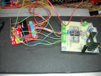
I'm using an L298 stepper controller like this one:
Stepper DC Motor Driver Board L298N Controller Module Based on L298N | eBay
I'll post the code now if anyone wants to look at it.
Although I'd rather wait till I get it working with the steppers and position sensors so I can get it debugged.
I'm using an L298 stepper controller like this one:
Stepper DC Motor Driver Board L298N Controller Module Based on L298N | eBay
I'll post the code now if anyone wants to look at it.
Although I'd rather wait till I get it working with the steppers and position sensors so I can get it debugged.
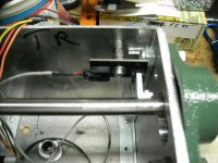
Opto-Coupler and Interrupter in place on the shaft.
The shaft is hardened to some extent, much more so than water harden drill rod. I busted off a 6-32 tap tonight tapping the hole for the screw to hold the interrupter in place.
It was a bugger to get out and re-tap and I spent most of the evening working on it but finally was able to clean it out and finish tapping it. I should be able to start on the buffer tomorrow, and begin testing the turns counter (redundant to the stepper count).
Attachments
The best....
Explain first what bandwidth you want, for which tube(or Ra), PP or SE and how low you want copper losses and core losses?
There is no "the best" if you not know what the design goal must be.
Explain first what bandwidth you want, for which tube(or Ra), PP or SE and how low you want copper losses and core losses?
There is no "the best" if you not know what the design goal must be.
Hi!
What would be the best winding method for a bifilar 1:1 interstage transformer?
Greets:
Tyimo
The heatsink on the stepper controller is way too small. I guess it is good for 3 or four watts max. If I am runing two motors at 2A each per winding with two windings, that is approaching 24W dissipation (figure 3V drop on the H-Bridge switches).
Question is whether use another heatsink, or find a way to mount it to the al plate and use it to carry away the heat.
Question is whether use another heatsink, or find a way to mount it to the al plate and use it to carry away the heat.
Attachments
20Hz-20KHz, 6N6P, Ra 1800 Ohm, SE, But the winding should be bifilar!Explain first what bandwidth you want, for which tube(or Ra), PP or SE and how low you want copper losses and core losses?
")
Greets:
Tyimo
That is no problem for me to make. Only the frequency respons will be much better then 20-20kHz
. Only the frequency respons will be much better then 20-20kHz20Hz-20KHz, 6N6P, Ra 1800 Ohm, SE, But the winding should be bifilar!
Greets:
Tyimo
Just ordinairy bifilar winding methode is good enough for your purpose. Not even in layers will work.
Than you can tell me: What would be the best (or a good) winding method for a bifilar 1:1 interstage transformer?
What about insulating? Between every row?Just ordinairy bifilar winding methode is good enough for your purpose. Not even in layers will work.
What about vertical sectionalizing??
Tyimo
If you want a sophisticated transformer with extreme bandwidth yes, other technics work better but you wanted just 20Hz- 20KHz so extra insulation or sections are not necessary, just 2 good copperwires.
What about insulating? Between every row?
What about vertical sectionalizing??
Tyimo
If you are really interested in transformer design i could send you some e-books:
- Audio transformers; Bill Whilock; 2001
- Electronic, transformers and circuits; Reuben Lee; 1947,1955
- Theorie der spulen und übertrager; Richard Feldtkeller,1957
First two book in english and the last in german
- Audio transformers; Bill Whilock; 2001
- Electronic, transformers and circuits; Reuben Lee; 1947,1955
- Theorie der spulen und übertrager; Richard Feldtkeller,1957
First two book in english and the last in german
What about, If I would want a sophisticated transformer with extreme bandwidth and low capacitance, etc??
it is depends on ratio of the transofrmation.
probably it is the good solution 1:1 interstage.
because that You dont have transfer of capacitances by the square root of ratio (which is =1)
core material is from the vital importance
alsi it depends of internal resistance of the generator. With high resistance generators like tubes, even in catode follower configuratins, You will need more Henrys, to acheive the low end.
That leeds itnto more turns on primaary, and secondaru. Implicating increase of the capacitances, involving more rinnging, and cutting the tops, disturbing the phsae at highs...
.
Generaly You need more space in core window and high permeability laminations
space is needed for insulation to try to beat capacitances, and higher permeability
decreses the number of turns for the desired primary inductance.
.
that is the case for the transformer with NO DC component in primary circle
DC current will saturate high-permeability cores.
.
So it is from the very importance in which position You want interstage xfrm
cheers
interstage for Ri=2300
I did some measurement at my interstage. This interstage is for tubes with a Ri=2300 (10mA-30mA dc).
I did some measurement at my interstage. This interstage is for tubes with a Ri=2300 (10mA-30mA dc).
An externally hosted image should be here but it was not working when we last tested it.
An externally hosted image should be here but it was not working when we last tested it.
An externally hosted image should be here but it was not working when we last tested it.
- Status
- This old topic is closed. If you want to reopen this topic, contact a moderator using the "Report Post" button.
- Home
- Amplifiers
- Tubes / Valves
- Designing an Interstage Transformer