There was a guy in Greece who posted his monster tube amp not long ago in the forum. He winds his own c-core inductors and he used some sort of wood+screws bracket to press the two halves together. I'm just saying, it can be done without the metal bands. I plan to use zip ties for prototyping.
Edit: but a quick look on epay shows some very affordable banding tools.
Edit: but a quick look on epay shows some very affordable banding tools.
I think this is a good reason to wind our own transformers.
Servicing of a Hiwatt DR405 400 Watt (Clone Amplifier
Servicing of a Hiwatt DR405 400 Watt (Clone Amplifier
The tool is $465. To me that is pricy.
Certainly it is not bad for a company producing a significant quantity of transformers. For one-off building it is prohibitive.
I use a screwdriver for my straps.
http://www.bridex.ch/schlauchschellen.html
Google Afbeeldingen resultaat voor http://www.blf-filter.de/bilder/spannband_03.jpg
Last edited:
I think this is a good reason to wind our own transformers.
Servicing of a Hiwatt DR405 400 Watt (Clone Amplifier
This is, for me, not the only reason, understand and know are powerful motive. In fact, I had done some toroidal transformer I soon will try, as I posted in a thread ad hoc. As the first attempt was failed, almost I know what I must NOT to the next time
")
I use a screwdriver for my straps.
BRIDEX AG - Schlauchschellen - UNEX, rostfreie Schlauchklemmen, Schlauchbriden, Spannbänder, Schnittbandkerne, Breitbandschellen, Gelenkbolzenschellen, stainless steel hose clamps, clamps, hoseclips, brides inox, brides
Google Afbeeldingen resultaat voor http://www.blf-filter.de/bilder/spannband_03.jpg
Great idea! Thanks!
I use a screwdriver for my straps.
BRIDEX AG - Schlauchschellen - UNEX, rostfreie Schlauchklemmen, Schlauchbriden, Spannbänder, Schnittbandkerne, Breitbandschellen, Gelenkbolzenschellen, stainless steel hose clamps, clamps, hoseclips, brides inox, brides
Google Afbeeldingen resultaat voor http://www.blf-filter.de/bilder/spannband_03.jpg
I thought so too, but I cringe, not knowing the material properties.
The metal strip follows the path of the magnetic field, without an air gap, it could reach saturation before the core itself, not good news.
I prefer to use L-shaped aluminum, and bolts, externaly.
This is, for me, not the only reason, understand and know are powerful motive. In fact, I had done some toroidal transformer I soon will try, as I posted in a thread ad hoc. As the first attempt was failed, almost I know what I must NOT to the next time
I chose the hard way, deduce formulas in a more reliable, from Maxwell's equations.
I got tired of books on transformers, "such is the constant for the equations work, blah, blah..."
Juan:
Maxwell's formulae doesn't speaks about parasitic inductances nor capacitances nor wiring resistances. They are a starting point, but as magnetic lines can't been see, they are useless in practical designs.
Certainly, sawing a lots of Argentine flags in the forum, in a short time, the rule about English Language must be changed to "Porteño Language", ja ja ja...
Un abrazo a los co-terráneos!
I thought so too, but I cringe, not knowing the material properties.
The metal strip follows the path of the magnetic field, without an air gap, it could reach saturation before the core itself, not good news.
I prefer to use L-shaped aluminum, and bolts, externaly.
I chose the hard way, deduce formulas in a more reliable, from Maxwell's equations.
I got tired of books on transformers, "such is the constant for the equations work, blah, blah..."
No problem in real world i think. Those strips are available in non magnetic stainless steel and if not, the permeability is to low to give any problems
Juan:
Maxwell's formulae doesn't speaks about parasitic inductances nor capacitances nor wiring resistances. They are a starting point, but as magnetic lines can't been see, they are useless in practical designs.
Ahhh ! Heresy !

James Clerk, forgive him, he knows not what he says...
consider brass straps, you can braze to them...
Or use higher temp and consequently stronger solders...
One could pull the cores by "other means" including large "hose clamps" and then having previously set up the ends of the brass band for a screw or similar assembly, tighten that in place to hold... there are variations on this scheme that will work... copper strap works too.
Btw, one can find new or used small size banding tools intended for shipping bands that ought to work ok with the proper thickness brass or copper strip... or stainless (non-magnetic).
You still need to squish the clamp thingie...
Last edited:
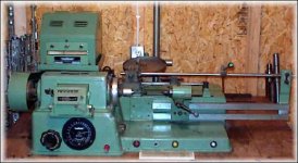
things like the winder shown (stock photo) show up on ebay and in local ads all over the place fairly often. You have to keep looking.
I have one of these Meteor 301 and a newer Meteor that has TTL digital control, with automatic acceleration and de-acceleration, turns counting... got that one from an outfit that sold welding supplies. They had been using it to spool welding wire! It was semi dead when I got it. Turned out to be a fried Vreg. Lucky in that regard. Had the schematic which was very good - the machine came with the original manuals, very good. So, it was obviously long term thermal excess that killed it. Re-did it with a 3 pin Vreg and put in a nice little outboard heatsink on the back of the controller chassis that I "borrowed" from the innards of a CRT computer monitor. Runs dead cool now.
Wish that copper wire was cheap like it used to be.
_-_-bear
Attachments
You are Sure their are just selling copper wire, or they also carry some other highly demanded agricultural product ?Not that much problem with papers, if you pay cash, but they heve no In ternet page, you must go there "in person" and see what they have available.
They fear robbery , so you will have to call them, make them trust you, and probably talk a lot through a 2" hole in their bullet proof door before they open it.
And even so, they may not sell you at all.
.
No, they definitely sell copper, but they are in a bad part of the city, betwen San Telmo and Constitución , and have been robbed at gunpoint before, held hostage, etc. so they don't take chances.
If you buy at *big* "Industry only" distributors like I often do, who do not sell to the general public, you'll see that all of them take similar precautions, and for good reason.
Same happens at Gregorio Galante in Avellaneda, where I buy the 30 sheet packs of MDF, Casa Goyo in Pompeya where I buy iron for speaker parts, the Car Parts Stampers who press my speaker frames/strap handles/corner protectors, the Electrical Distributor where I buy rolls of wire, 220V plugs by the 300 unit case and so on.
"Insecurity" is NOT a Clarín newspaper invention.
All places I mentioned hold more cash at their offices than a regular Bank has at the Cashier's desks, and thieves know that very well.
EDIT: @ bear:
Hey!!, what a nice winder!! Looks much more than a CNC controlled lathe than a simple winder, cool !!!
Last edited:
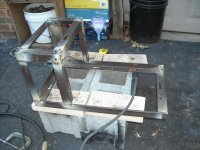
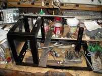
Welding Frame
Bear that is one sweet winder.
If this works out, I hope to add steppers later and an Arduino to control it.
I welded the basic frame welded this morning and need to do grinding clean up now.
Unfortunately for the project, nice weather is here (supposed to hit 65F/16.3C today) and the sun is out so I will have to work in the yard.
Attachments
How big of a Stepper?
I've been thinking about driving the spindle and was originally going to use a 240r/m gear-head motor.
However, I have was rummaging through one of my bins and found a stepper that appears to be a NEMA34 size motor.
It is a Step-Syn by Sanyo Denki rated at 1.7V 2/4A, 2 degrees/step.
Measured inductance is 2.35mH.
It has eight leads which ohm out to four pairs so it is most likely could be configured as either unipolar or bipolar.
Does anyone have experience with stepper motors that can tell me if this looks like an appropriate size motor to drive the spindle?
Last edited:
I may starting over on my winder. I've been offered an X-Y plotter table by a friend and it will be interesting to see what steppers it has.
For those of us in the USA, we now have a source for E-I cores at what appears to be a very reasonable rate.
I just ordered the EI100s
https://www.edcorusa.com/c/116/lamination
For those of us in the USA, we now have a source for E-I cores at what appears to be a very reasonable rate.
I just ordered the EI100s
https://www.edcorusa.com/c/116/lamination
- Status
- This old topic is closed. If you want to reopen this topic, contact a moderator using the "Report Post" button.
- Home
- Amplifiers
- Tubes / Valves
- Designing an Interstage Transformer