I wish to design and construct an interstage transformer for an SET amplifier using a 6A5 or 6B4G.
Driving tube will be a 6N7 with both plates in parallel for an effective RP of around 5500R.
Max bias current will be 10mA.
I just finished reading chapter 5 of RDH4, and plan on re-reading it. I've also been reading other works about transformers in general.
I'm probably going to have a lot of questions, but will try to go through the design process.
The cores I have are stripped from a set of24W line matching transformers. The laminates weigh 556gr per set.
The cores are loss-less EI cores with an I measurement of 1.122cm X 6.692cm by .45mm thick.
Tongue width is 2.23cm
Stack height is 2.57cm
Window is 1.05cm by 3.0cm (with the bobbin I made installed)
The cores are probably marginal for the project, however I have them so I plan on using them for a first iteration design.
estimated MLP 15.35cm
estimated MTL 14.021cm
Step 1. Calculate required inductance based on minimum frequency response and the driving tube plate resistance and drive voltage to the grid of the output tube (35Vrms).
Rp=5500R
F1=10Hz (yea, aggressive)
Use Xl=5* Rp = 5* 5500R =27500
Xl=2* PI * 20 * L
L = XL/(2 * PI * 10)
L = 27500/(2 * PI * 10) = 218 H
This is the first problem. It may be necessary to abandon the 6N7 for the 6SN7 with an Rp of 3850 for parallel plates, which would cut the inductance requirement to 152H.
So, is this correct so far?
It is VERY difficult to make an IT with that high inductance that isn't anything than a muddler. (It will have horrible high frequency response and muddle your sound).
However I don't believe winding ITs and OTs is such a mytical black art as so many claim. The trick is having the proper tools, such as a winder of some sort that lets you wind with proper tension and that lets you lay the wire nicely along the bobbin. Doing a few transformers you can probably get decent tension simply by hand feeding, but for how many turns?...
Interleaving and winding layers to be with as low capacitance as possible isn't easy, but doable. You'll need patience to run some test windings if you only want the best. I don't think the cheaper manufacturers like EDCOR does much fancy interleaving and other techniques in their transformers.
I think for one you really need to relax your specs. Why 5xRp? 10Hz as low end goal is admireable, but is there really that much to gain in happiness? Better to aim for 20 or even 30Hz and get better wide band response IMHO.
Anyway, hope you give it a try. I've just bought some left over amorphous cores for same idea, interstage trannies, but will use lower Rp tubes like 6922 and trioded 6W6s. I think you core size is plenty for this useage. As you know you need some air gap since it'll be SE, and that'll require even more turns to make the Henrys. Good luck.
Oh, what size wire are you using?
The trick is having the proper tools, such as a winder of some sort that lets you wind with proper tension and that lets you lay the wire nicely along the bobbin. Doing a few transformers you can probably get decent tension simply by hand feeding, but for how many turns?...
IMHO the trick is experience and knowledge. Winding machine, proper laminations and wire can be bought. But the technique to get the lowest stray capacitance is based on experience and skill.
I have to say you are starting with probably the most difficult audio trans to wind imho.
For good performance from interstage driver transformers, bi-filar windings are by far and away the best method to get good bandwidth, but you will need high quality double insulated wire, and v good winding technique to reduce risk of primary to secondary breakdown.
I would suggest your best bet is to buy commercial from Hammond, Audio Note or Monolith Magnetics.
Best of luck
he, a few months ago I began to construct my own amp box handles
basicly because I thougt the were way too expencive
and sometimes too much work to find the right one
scrapped some, but have had my share of fun doing it
and I can now make one in no time
but learning how to wind a trafo probably takes a bit longer
basicly because I thougt the were way too expencive
and sometimes too much work to find the right one
scrapped some, but have had my share of fun doing it
and I can now make one in no time
but learning how to wind a trafo probably takes a bit longer
1. If cost were the only consideration I would buy transformers. Considering I will need a winding jig (Make or buy is still a question), and in time more laminates wire, etc this is not cost effective per se.
I am doing this because I wish to learn. I am going back and studying things I forgot years ago.
2. Thanks for the input on winding technique, however for now I would prefer to stick to the electrical design and once finished move on to issues like interleave, segmentation, multifilar winding, etc.
Back to design.
To address Simper-Fe's questions:
5 X Rp was chosen as I understood that for inductor loading, one would normally like to have load impedance 5X Plate resistance. If this is not necessary I can relax this spec.
Why 10Hz, because the design example I was reading used that value. With this core I am sure I will have to make compromises, but for a first pass calculation. So, I'll recalculate with 20Hz which is more typical of F1 for audio amps any way.
Wire size will be addressed as part of the design but in a later phase.
So back to the design.
there was a miss-calculation in the first post. Using 5XRp and 10Hz should give 436H instead of 218H. 218H is correct for F1=20Hz
Calculating N we re-arrange the equation:
L=(3.2 * N * N * u * A )/ (10^8 * l)
solving for N one has :
N = SQ-RT (L * 10^8 * l )/(3.2 * u * A)
The cores dimensionally look real close to EI-87 (26guage), and may be.,so I'll use that data. The fact that they were used for line transformers gives a high probability they are GOSS but low silicon content.
u of 4% GOSS is around 5000
u of steel is around 300
so a conservative guess would be u=1000 for these cores.
l (MLP) = 15.35cm
A = 0.88sq in ~= 5.68sq-cm
this yields: 13568 Turns!!! Yikes, this is not going to happen.
So, where to start making compromizes?
1) What is a reasonable value for XL if not 5X Rp?
Is XL = Rp reasonable? It meets maximum power transfer theorum.
2) Is u=1000 reasonable or should it be higher?
But this is diy isn't it? If any one here does diy to save money I think they picked the wrong hobby.
Not generally true. While difficult, one can build an 833A amp for less than one can buy a wavac.
")
[1] there is no such thing as a "lossless" E-I core.
[2] 10 Hz spec ... is just silly. SemperFI is right on this. Shoot for 17 Hz or 20 Hz
[3] Bifilar winding is a must have aspect of this proposed transformer. The enhancement of both top-end and mid-range coupling is substantial, and desired.
[4] Your biggest "problem" will be core saturation, regardless of whatever henry-value you choose for the windings. Its real, and it sucks.
[5] Because of [4], you'll find in turn that you'll likely have to compromise the low end rolloff.
[6] And... while you're using transformers as interstage coupling devices ... you will want to look at using tri- or tetra- filar windings ... so that you might step UP the output of stages for that grand old coupled-inductor voltage-amplification effect. Its useful, it works, and that's what the attraction is to using transformers.
[7] Or, though difficult, consider using separate insulated overlapped layering. Since the transformer is a one-off (i.e. you're not in production!) the extra labor of winding one layer of primary, then 1 layer of secondary (with a different wire gauge and # of windings), then a paper gap, and another primary, and another secondary, and another paper gap, and so on ... until the desired primary/secondary is built up ... isn't all that bad. Better control of interwinding capacitance.
Well there you are. I'm happy indeed to no longer be winding my own transformers. There is just so much MORE one can do to become happy with electronics than this particularly odious task.
GoatGuy [PS: Jensen ... are good people. They make great transformers.]
1. If cost were the only consideration I would buy transformers. Considering I will need a winding jig (Make or buy is still a question), and in time more laminates wire, etc this is not cost effective per se.
I am doing this because I wish to learn. I am going back and studying things I forgot years ago.
2. Thanks for the input on winding technique, however for now I would prefer to stick to the electrical design and once finished move on to issues like interleave, segmentation, multifilar winding, etc.
Back to design.
To address Simper-Fe's questions:
5 X Rp was chosen as I understood that for inductor loading, one would normally like to have load impedance 5X Plate resistance. If this is not necessary I can relax this spec.
Why 10Hz, because the design example I was reading used that value. With this core I am sure I will have to make compromises, but for a first pass calculation. So, I'll recalculate with 20Hz which is more typical of F1 for audio amps any way.
Wire size will be addressed as part of the design but in a later phase.
So back to the design.
there was a miss-calculation in the first post. Using 5XRp and 10Hz should give 436H instead of 218H. 218H is correct for F1=20Hz
Calculating N we re-arrange the equation:
L=(3.2 * N * N * u * A )/ (10^8 * l)
solving for N one has :
N = SQ-RT (L * 10^8 * l )/(3.2 * u * A)
The cores dimensionally look real close to EI-87 (26guage), and may be.,so I'll use that data. The fact that they were used for line transformers gives a high probability they are GOSS but low silicon content.
u of 4% GOSS is around 5000
u of steel is around 300
so a conservative guess would be u=1000 for these cores.
l (MLP) = 15.35cm
A = 0.88sq in ~= 5.68sq-cm
this yields: 13568 Turns!!! Yikes, this is not going to happen.
So, where to start making compromizes?
1) What is a reasonable value for XL if not 5X Rp?
Is XL = Rp reasonable? It meets maximum power transfer theorum.
2) Is u=1000 reasonable or should it be higher?
Watch out !
In SE have DC circulation, you should consider an air gap !
I hope some of this would be useful
http://www.diyaudio.com/forums/tubes-valves/181072-designing-transformers-j-c-maxwell.html
I have to say you are starting with probably the most difficult audio trans to wind imho.
For good performance from interstage driver transformers, bi-filar windings are by far and away the best method to get good bandwidth, but you will need high quality double insulated wire, and v good winding technique to reduce risk of primary to secondary breakdown.
I would suggest your best bet is to buy commercial from Hammond, Audio Note or Monolith Magnetics.
Best of luck
Hammond 126C and 126B , to me sound superb for a £30 a piece lump of iron . These bifilar 1:1 IT are a bargain , probably the biggest bang for buck out there
316A
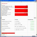
I've been using the formulas from here:
Transformer Math
In his example he used plate load of the transformer as 5 X Rp.
I've been typing the equations into a spreadsheet.
I'm now using u=4000 and lg= 0.0076cm (.003")
I get a ue of 1340.
Here are a screenshot and a zip of the spreadsheet
Transformer Math
In his example he used plate load of the transformer as 5 X Rp.
I've been typing the equations into a spreadsheet.
I'm now using u=4000 and lg= 0.0076cm (.003")
I get a ue of 1340.
Here are a screenshot and a zip of the spreadsheet
Attachments
Well there you are. I'm happy indeed to no longer be winding my own transformers. There is just so much MORE one can do to become happy with electronics than this particularly odious task.
I found you have to try and keep things tidy. Keep the tension the same. Lay the windings next to each other neatly.
For dual secondaries wind both at the same time to keep inductance the same.
I have done loads of class d output coils.
I have also done quite a few SMPS transformers.
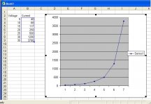
OK, Since I don not know the permeability of the core I figure I should measure it so we can all agree on a value.
I used a variac to drive the 16R secondary to common taps. I measured the current using a 1R sense resistor. I will strip the windings and count them once I have sufficient data. From the number of turns and the current I can get the Ampere-Turns at saturation
Readings were taken at 5V intervals.
1) Is this sufficient data to get an accurate measure of permeability?
2) Where on the curve does one define saturation since it is not a step function?
Current doubled from sample 6 (30V) to sample 7 (35V). Is 30V then a good point to chose? Should I take more readings between 25 and 35V?
I also tried measuring it with a 100W light bulb between the variac and transformer. When I got to 20V the lamp came on and the voltage across the transformer didn't change but 4V as I increased the variac to 125V out. From that it looks like saturation occurs at 20V.
If permeability is the slope of the BH curve, it seems I should get more readings below 25V and calculate around 15 V.
Attachments
Last edited:
- Status
- This old topic is closed. If you want to reopen this topic, contact a moderator using the "Report Post" button.
- Home
- Amplifiers
- Tubes / Valves
- Designing an Interstage Transformer