I did some measurement at my interstage. This interstage is for tubes with a Ri=2300 (10mA-30mA dc).
An externally hosted image should be here but it was not working when we last tested it.An externally hosted image should be here but it was not working when we last tested it.An externally hosted image should be here but it was not working when we last tested it.
That looks nice!
If you don't mind I would be interested in the Whilock book you mentioned in the previous message.
")
- Electronic, transformers and circuits; Reuben Lee; 1947,1955
- Theorie der spulen und übertrager; Richard Feldtkeller,1957
Hi!
For these two I would be interested. Thanks!
BTW.: Nice measurement. What about the phase?
Greets.
Tyimo
I guess phase would be also very good but i didn't measure it. Can't measure it anymore because i sold the IT now. Maybe i will make some new IT and try to make it even better.
Electronic Transformers and Circuits : Reuben Lee : Free Download & Streaming : Internet Archive
Audio Transformers - Audio Transformers IG Präzisions-Wickeltechnik
Electronic Transformers and Circuits : Reuben Lee : Free Download & Streaming : Internet Archive
Audio Transformers - Audio Transformers IG Präzisions-Wickeltechnik
Hi!
For these two I would be interested. Thanks!
BTW.: Nice measurement. What about the phase?
Greets.
Tyimo
The c-core on the photo is a SG70/32 double c-core. This a "77W" 50Hz core.
I use M0 core material (or as i call it HiB) 0,23mm.
The "power" is not the right word for a SE audiotransformer. All depends of frequency, pre-magnetisation, induction (H) and losses etc.
I use M0 core material (or as i call it HiB) 0,23mm.
The "power" is not the right word for a SE audiotransformer. All depends of frequency, pre-magnetisation, induction (H) and losses etc.
Thanks!
What kind of C-core are you using?
How do you determine the power rating of an intersatge transformer?
For example: Ri: 1800Ohm, 15mA, B+:100 Vdc
Tyimo
For an inter-stage transformer one is more constrained by Rp of the driving tube and hence required inductance, turns ratio if other than 1:1, and winding window area than power rating.
For instance I am trying to design a 1:1 IT to be driven by a 6N7 at <10mA (5mA) Ia.
Static dissipation as currently designed with 34AWG wire is roughly calculated based on copper loss from about 1250 feet of wire at 271Ohms /1Kft or 339R.
At 5ma this should be .005 * .005 * 339 = 8.5mW.
If the RMS output voltage is 35V, we add 35*.005 = 0.175 W
total is roughly 185mW.
The core will support well over 10 times that in SE configuration.
So here one is constrained by factors other than power dissipation.
Thanks!Static dissipation as currently designed with 34AWG wire is roughly calculated based on copper loss from about 1250 feet of wire at 271Ohms /1Kft or 339R.
At 5ma this should be .005 * .005 * 339 = 8.5mW.
If the RMS output voltage is 35V, we add 35*.005 = 0.175 W
total is roughly 185mW.
I was interested how do you choose the suitable iron size.
Greets:
Tyimo
The process is basically :
1 Determine the driving and load source impedance.
2 Calculate the inductance necessary to support the lower F3 response point
3 Guestimate the size core and stack size you will need
4 Calculate the number of turns needed to produce the needed inductance
5 calculate the wire size needed to support the DC current and acceptable DCR
6 calculate the required winding window area needed with the chosen wire size and see if it will fit in the available window area
If not, go back to 3 and try again until an acceptable result is found.
Not forget
- how much pre magnetization you want.
- maximimum magnetization you want
- how much pre magnetization you want.
- maximimum magnetization you want
The process is basically :
1 Determine the driving and load source impedance.
2 Calculate the inductance necessary to support the lower F3 response point
3 Guestimate the size core and stack size you will need
4 Calculate the number of turns needed to produce the needed inductance
5 calculate the wire size needed to support the DC current and acceptable DCR
6 calculate the required winding window area needed with the chosen wire size and see if it will fit in the available window area
If not, go back to 3 and try again until an acceptable result is found.
I'm still playing with the code, but figured I'd go ahead and post it.
I think this is almost complete. I am debugging the traverse motor routines with code to either wind back and forth, or only in one direction with a return to home for the next layer (Left to right winding only).
The layers, segments and turns seem to be right.
Comments welcome.
And,...
No, fortunately I don't write code for a living.
This is pretty much spaghetti code.
Attachments
Looks like I have major system problems on my main system at home. The C: drive continually seeks during the early boot phase, and after coming out of post, it does nothing.
I replaced the C: drive with another spare that already had XP Pro installed and it booted. I shut it down last night and when I went downstairs this morning it was stuck showing bios boot sequence and nothing more. I tried resetting it and got same symptom so it looks not good.
I'll swap the PS tonight and hope it is the problem.
Last back-up was two months ago so I won't lose too much data, however all the application programs will have to be re-installed.
Bleh!
PS went to 16V+ on the 12V line.
OS drive is toast. I use one drive for OS and programs and a second drive for data. I find It is easier to back up my data that way, but in this case I've lost everything in my download directory, and a bunch of LTspice stuff.
The Data drive can still be accessed when installed in another system so that is good.
I don't know if the second XP pro OS drive is good or not. I won't know until I get a new PS as it is an SATA and the other system I tested the data drive on does not support SATA.
I've ordered another power supply and hope the os drive was the only casulty.
Posts during the day are from werk.
I am operating on a small linux system at home in the interm.
New power supply arrived.
No screen start-up, no Post, no drive seek, no nada.
Looks like the ps over-voltage took out everything except possibly the data drive.
I'll have to try to transfer the data off the other drive if I can still access it. It is an old IDE drive so I only have one remaining system in the house that can support it.
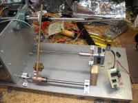
Traverse Arm and Wire Guide
Computer was a total loss.
Tyimo, I'm sorry but I have no idea.
I've been distracted and busy at werk so progress has been slow on the winder.
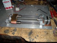
Here are the latest shots. I'm working on the traverse mechanism.
I'm at odds as which way to drive it. Low is easier to set up, but I believe high will give more regidity to the arm.
I'm using two pulleys so I can wind bifilar.
Computer was a total loss.
Tyimo, I'm sorry but I have no idea.
I've been distracted and busy at werk so progress has been slow on the winder.
Here are the latest shots. I'm working on the traverse mechanism.
I'm at odds as which way to drive it. Low is easier to set up, but I believe high will give more regidity to the arm.
I'm using two pulleys so I can wind bifilar.
Attachments
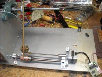
May I suggest that you add another linear guide to your traverse mechanism? That´s what I did in my machine, with two guides and one screw the whole assemly became rock solid, in opposite to how it was with only one guide.
The control system for my machine is now up and working thanks to my friends. There is plenty of room for improvements but now I can set the number of turns, traverse direction and wire thickness (in 0,01mm increments) in a simple menu system. Later on we´ll try to incorporate an rotary encoder for data input and jogging.
The control system for my machine is now up and working thanks to my friends. There is plenty of room for improvements but now I can set the number of turns, traverse direction and wire thickness (in 0,01mm increments) in a simple menu system. Later on we´ll try to incorporate an rotary encoder for data input and jogging.
- Status
- This old topic is closed. If you want to reopen this topic, contact a moderator using the "Report Post" button.
- Home
- Amplifiers
- Tubes / Valves
- Designing an Interstage Transformer