hi guys,
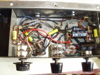
new here, this is my first post,,,, i just rebuilt my first amp,a little zenith 3L03, new caps, resistors, polarized cordset & stdp switch.... i redressed the filament leads, and put in a 3rd stage filter, to help get rid of teh hum,,, it works pretty well, the amp has crisp highs, but not a lot of bass, and it has some distortion, at high volume levels...
the distortion is what i'm trying to reduce now,,,the tubes all test very good ... i modded teh amp a little,,, replaced teh .01 coupling caps with .068, in hope of getting more bass, it helped a little, but seems to have maxed out there...
i replaced teh 150 ohm K resistors with 180's,,, and dropped teh 270K coupling resistors, to 220K,,,tried as low as 120K, to get more negative bias, but it didn't seem to change after 220...
i would appreciate any help i can get to get rid of teh distortion, or at least to understand why its there,,,
i posted teh original schematic,,, and teh chassis..
thanks for reading,
regards,
john
(schematic removed by moderators for blatant safety issues)
Attachments
From my quick look at the schematic and not knowing even 1/10th as much as the other regular posters here at diyaudio, I can say that it is pretty underpowered but nonetheless pretty cool.
You are getting all your power from 110 V from the wall, with no power transformer required (the tubes are at 117V according to the schematic), so I wouldn't think that you would be able to get massive amounts of volume from this setup because of small tubes, low B+ voltage, SE set up, all usually means low power.
You might not get much bass response because this looks like it was set up for playing records -- I was told that there is something about records not having very low frequency range because of something or another, (I am not very knowledgeable when it comes to this stuff, I can build it, and I am still alive) only as I don't see an auxillary in and only the phono cartridge in.
The only thing I can think of is upgrading to beefier output transformers (but that requires math and money to figure out what would be appropriate). It might not be worth it, but see what the experts here have to say.
What kind of speakers are you using? Are you using other than the original ones which are rated for 9 ohms and probably as old as the hills?
FIRST THING- install an isolation transformer. This setup is dangerous enough that we have a specific rule on this forum about showing anything with a direct mains connection.
i am running it thru an isolation transformer... plugged into a gfi receptacle... i have been a licensed electrician for over 40 years, and am aware of teh hot chassis design,, same as most AA5 radios.... this is the only tube amp i have, and am using it to learn about tube circuits,,, i have plans to restore, or build my own 5 tube amp, i found a schematic to use....
if i can't discuss it on your forum, please let me know... i will remove the info in the post...
thank you,
john
hi thanks for your reply,
hi thanks for your reply,
yes, it is from a zenith portable phono,,, i have it connected thru a cd palyer, now,,, and used it with a casstte player, also...
i was told that different OT's may help teh bass, but i don't know how to calculate what i would need...
i'm running thru my main speakers(12"-4" tweeter, in a bass reflex enclosure)... it came with 3x5" but sounds much better pushing teh bigger speakers,,, also, teh output of teh amp is 3.2 ohms,,, my mains are 8 ohm...
regards,
john
From my quick look at the schematic and not knowing even 1/10th as much as the other regular posters here at diyaudio, I can say that it is pretty underpowered but nonetheless pretty cool.
You are getting all your power from 110 V from the wall, with no power transformer required (the tubes are at 117V according to the schematic), so I wouldn't think that you would be able to get massive amounts of volume from this setup because of small tubes, low B+ voltage, SE set up, all usually means low power.
You might not get much bass response because this looks like it was set up for playing records -- I was told that there is something about records not having very low frequency range because of something or another, (I am not very knowledgeable when it comes to this stuff, I can build it, and I am still alive) only as I don't see an auxillary in and only the phono cartridge in.
yes, it is from a zenith portable phono,,, i have it connected thru a cd palyer, now,,, and used it with a casstte player, also...
The only thing I can think of is upgrading to beefier output transformers (but that requires math and money to figure out what would be appropriate). It might not be worth it, but see what the experts here have to say.
What kind of speakers are you using? Are you using other than the original ones which are rated for 9 ohms and probably as old as the hills?
hi thanks for your reply,
yes, it is from a zenith portable phono,,, i have it connected thru a cd palyer, now,,, and used it with a casstte player, also...
i was told that different OT's may help teh bass, but i don't know how to calculate what i would need...
i'm running thru my main speakers(12"-4" tweeter, in a bass reflex enclosure)... it came with 3x5" but sounds much better pushing teh bigger speakers,,, also, teh output of teh amp is 3.2 ohms,,, my mains are 8 ohm...
regards,
john
Since you've clearly stated that you use an isolation transformer this discussion can continue.
ok,,, well, i see teh schematic was taken down,,, am i allowed to pm it to someone who may offer to help me out?
tahnks,
john
Might help to post a hand drawn schematic of the amp which must clearly show the isolation transformer as part of the circuit.
Edcor makes some nice output transformers, but I suspect even their small ones might be a bit too large for this tiny chassis.
I would enjoy as is, and if you really like tube sound consider this: Simple SE
George is quite active here and a friend to many - I can highly recommend this as a project for a tube newb.
Performance will be immeasurably better, providing real bass, dynamics and detail with enough power to get some decent levels out of your speaker system.
ok,,, well, i see teh schematic was taken down,,, am i allowed to pm it to someone who may offer to help me out?
tahnks,
john
No problem there, but you could draw it yourself and snap a picture with your digital camera, not brilliant but it would work to get the information across.
No problem there, but you could draw it yourself and snap a picture with your digital camera, not brilliant but it would work to get the information across.
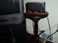
ok,,, heres a pic of the amp and teh iso trans is under the table...
i tried to post schematic pics i took with my camera, they came out to blurry to read...
thanks, also for teh link to teh "simple se",,, i have a 6v6 amp in mind, i have the tubes, and a chassis i built, i'm not really interested in pc board construction...
i sure hope this thread gets pointed to teh distortion problem i first asked about!!!!!
regards,
john
Attachments
Distortion is mainly caused by mispolarization of the tubes, check the cathode resistors, and their corresponding voltages. 12AX7´s usually need between 1 and 2 volts of bias, no much more not too less.
The output stage is in push pull or SE? In case of true push pull, you can remove the cathode bypass cathode capacitor and improve linearity.
Good luck!.
The output stage is in push pull or SE? In case of true push pull, you can remove the cathode bypass cathode capacitor and improve linearity.
Good luck!.
knockbill, if you can get the original from the factory Zenith schematic back up, just take a purple marker and draw a 110 tranny over the plug in the diagram because this is going to go all over the place (PP? SE? Triode? Pentode? etc.?) without that schematic.
Try what Osvaldo de Banfield says up there, but I am thinking that you are going to be ultimately limited by the size of your output transformers.
Also, the speakers might be a little too much for the amp to push unless they are very efficient speakers. Might want to try some more efficient ones (90 - 92 db sensitivity) if you have a pair or can borrow a pair.
And I agree with kevinkr that George at tubelab is one of the ways to go for something tube sounding. His PCBs are real nice, descriptive step by step instructions, designs are flexible (depending on how you want to set up the amp, you will have a lot of point to point soldering for choice of biasing, going from triode to ultralinear, and whatever else... so there are many options that you can build into it) and he is a really interesting tube amplifier designer and builder. Take a look at this amp he made:
The 833A SE Amp Prototype
72 pounds of running hot transformer! 1,500 volts! THAT already is mind blowing. His comment of, "Let's try to blow something up!" and getting out a Lexan shield speaks volumes of how well tested these boards are. And his method of testing is pure awesome to read (read test #6 down the page). And this is off one of his SE printed circuit boards that he has for sale (not the Simple SE though).
But don't be discouraged, your 117 volt SE amp probably won't produce as much SE amp power as George's 1,500 volt SE amp, but it is a good starting point for tubes.
Or you could try the RH84 design as a good starting point in SE design with a 300-0-300 transformer.
Distortion is mainly caused by mispolarization of the tubes, check the cathode resistors, and their corresponding voltages. 12AX7´s usually need between 1 and 2 volts of bias, no much more not too less.
The output stage is in push pull or SE? In case of true push pull, you can remove the cathode bypass cathode capacitor and improve linearity.
Good luck!.
thanks for your reply,,, it took two pages to get some answers!!!!!
i will try to pm teh schematic to you, if you are interested,,, which pins do i measure teh 12ax7 bias on? i believe this is a SE amp,,, it only has the 12ax7 and a single 50c5 for each channel...i measured -5.2V between pins 1 and 2 of teh 50c5's...i read where -7V is ideal...
thanks again,
regards,
john
Last edited:
"
Maybe an old Magnavox console will fall into my lap!!!!
Regards,
John
knockbill, if you can get the original from the factory Zenith schematic back up, just take a purple marker and draw a 110 tranny over the plug in the diagram because this is going to go all over the place (PP? SE? Triode? Pentode? etc.?) without that schematic."
Not sure how I can draw on teh schematic, and get it back on a post,,, if I take a pic of it, it won't be ledgible, I tried it before...Besides the moderators took it off
"Try what Osvaldo de Banfield says up there, but I think that you are going to be ultimately limited by the size of your output transformers."
I believe you are correct,, I have to do some research on OT's, I guess...I did reply to his post, hope he responds....
"Also, the speakers might be a little too much for the amp to push unless they are very efficient speakers. Might want to try some more efficient ones (90 - 92 db sensitivity) if you have a pair or can borrow a pair."
Possibly, they are from teh 60's,, i built Walnut cabinets for them in high school... they are Knight kit I, believe, from Allied radio,IIRC ...and enclosed Magnavox tweeters.. they sound good , with this little amp,, but really come to life with the Sansui...
"And I agree with kevinkr that George at tubelab is one of the ways to go for something tube sounding. His PCBs are real nice, descriptive step by step instructions, designs are flexible (depending on how you want to set up the amp, you will have a lot of point to point soldering for choice of biasing, going from triode to ultralinear, and whatever else... so there are many options that you can build into it) and he is a really interesting tube amplifier designer and builder. Take a look at this amp he made:"
The 833A SE Amp Prototype
"72 pounds of running hot transformer! 1,500 volts! THAT already is mind blowing. His comment of, "Let's try to blow something up!" and getting out a Lexan shield speaks volumes of how well tested these boards are. And his method of testing is pure awesome to read (read test #6 down the page). And this is off one of his SE printed circuit boards that he has for sale (not the Simple SE though)."
"But don't be discouraged, your 117 volt SE amp probably won't produce as much SE amp power as George's 1,500 volt SE amp, but it is a good starting point for tubes."
You are correct,,, and learning tube amps is teh exercise here...
"Or you could try the RH84 design as a good starting point in SE design with a 300-0-300 transformer."
Maybe an old Magnavox console will fall into my lap!!!!
Regards,
John
Attachments
Last edited:
I see 2 issues that pertain to your distortion issue. First you state the output transformer has a 3.2 ohm secondary impedance, basically the nominal impedance of most 4 ohm speakers of the day. The 50C5 is intended to use a 2.5k ohm primary and using an 8 ohm instead of 4 will double the primary impedance (5k) causing 2 things to happen. 1) Power output will be reduced from the rated 2.3 watts to 1.9 and (2) the distortion will increase from the rated 10% up to 17%. These are values directly from the datasheet.
The second issue, you stated that there is only a bit over 5 volts on the cathode of the 50C5's. This either means the cathode resistors are the wrong value or your added filter in the B+ supply has reduced the plate voltage a fair amount. Both of these things would again cause loss of output power and increased distortion by changing the nominal operating conditions. For the cathode resistors use two 270 ohm in parallel. If your filter is reducing the B+ to much, I assume its a RC type, try using a much lower value resistor with a larger capacitor to restore B+ back up to 110-120 volts.
Moderators, would it be ok for the OP to post a schematic of only the amplifier section without the power supply?
A list of the voltages at the plate/grid/cathode referenced to ground of each tube would be helpful as well.
Last edited:
I found your post on AudioKarma with the schematic. A modification I would immediately make would be to either get rid of the balance pot and use fixed resistors or add resistors from the grids to ground. Reason being that if the wiper on the balance pot loses contact, which happens with old ones like this, the output tubes will lose bias and possible self destruct. I personally would ditch the tone control too,but thats my preference. If the scriblings on the schematic are changes you made then increasing the cathode bypass caps to say 220uF will help with the bass some as well. Adding a tuned feedback network to enhance the bass end can also be done, since it has no feedback I imagine it has a fairly high gain as is.
I see 2 issues that pertain to your distortion issue. First you state the output transformer has a 3.2 ohm secondary impedance, basically the nominal impedance of most 4 ohm speakers of the day. The 50C5 is intended to use a 2.5k ohm primary and using an 8 ohm instead of 4 will double the primary impedance (5k) causing 2 things to happen. 1) Power output will be reduced from the rated 2.3 watts to 1.9 and (2) the distortion will increase from the rated 10% up to 17%. These are values directly from the datasheet.
The second issue, you stated that there is only a bit over 5 volts on the cathode of the 50C5's. This either means the cathode resistors are the wrong value or your added filter in the B+ supply has reduced the plate voltage a fair amount. Both of these things would again cause loss of output power and increased distortion by changing the nominal operating conditions. For the cathode resistors use two 270 ohm in parallel. If your filter is reducing the B+ to much, I assume its a RC type, try using a much lower value resistor with a larger capacitor to restore B+ back up to 110-120 volts.
Moderators, would it be ok for the OP to post a schematic of only the amplifier section without the power supply?
A list of the voltages at the plate/grid/cathode referenced to ground of each tube would be helpful as well.
I guess we're kind of crippled here,,, but i do appreciate your help,,, i'll do my best to give you the info.... here are teh tube voltages, i just got them, pinouts to chassis grd....
thanks again for your input...
regards,
john
K Grid Grid2 Plate
50C5 ,,,,,,,,,,,,6.6,,,,,,,,, 0 to -2 ,,,,,,,, 94 ,,,,,,,,,,,,,, 109
50C5 ,,,,,,,,,,,,6.6,,,,,,,,, 0 to -1 ,,,,,,,,, 94,,,,,,,,,,,,,,, 109
12AX7,,,,,,,,,,, .6,,,,,,,,,, 3.6 ,,,,,,,,,,,,,,,,,,,,,,,,,,,,,,,,,,,, 48.3
,,,,,,,,,,,,,,,,,,,,,, .6,,,,,,,,, , 4.0 ,,,,,,,,,,,,,,,,,,,,,,,,,,,,,,,,,,, 48.4
Last edited:
I found your post on AudioKarma with the schematic. A modification I would immediately make would be to either get rid of the balance pot and use fixed resistors or add resistors from the grids to ground. Reason being that if the wiper on the balance pot loses contact, which happens with old ones like this, the output tubes will lose bias and possible self destruct. I personally would ditch the tone control too,but thats my preference. If the scriblings on the schematic are changes you made then increasing the cathode bypass caps to say 220uF will help with the bass some as well. Adding a tuned feedback network to enhance the bass end can also be done, since it has no feedback I imagine it has a fairly high gain as is.
Glad you found the schematic,,,there's a complete rebuild thread on there also....Did you see the input filter on teh schem? its highlighted in pink,,, its not on my amp...
I posted the "new" voltage readings,,,they are actually closer than i originally stated,,,
i read K voltage between pins 1 &2, due to an article i saw.. it seemed to throw everything off... the new readings are accurate...
I'd hate to loose the balance control, due to teh room layout,,, maybe replace it with a new one?
Let me know what you think of the tube readings,,, don't want to start changing stuff, until its sorted out..,
thanks for your help,
john
- Status
- This old topic is closed. If you want to reopen this topic, contact a moderator using the "Report Post" button.
- Home
- Amplifiers
- Tubes / Valves
- rebuilding 3tube zenith amp