Hi All,
I have been lurking here for a while and learnt plenty reading the topics here.
I have a couple of EL84 push-pull amps that I bought off fleabay a while ago, they are supposed to be "Suppo" but their internal layout and schematic seems a lot different to ones I've seen posted here.
I've managed to work out why they've chosen most of the values on the board, but I can't work out why they have 10K screen resistors, so when it's running normally with 300V B+, the screens are only seeing ~250V.
Would there be a technical reason for this? Does this suppress the valve/tube from providing its full output? Finally, would there benefits in raising the G2 voltage closer to what the EL84 spec sheet says for class AB PP operation? (which is 300V B+ & 300V G2). Should mention that it's currently running the std Chinese 6P15s.
cheers!
Jacob
It may not be universally applicable, but I know of at least two designers (Gary Pimm and Peter Millet) who have measured lower distortion with shared screen resistors.
307A Push-Pull Amp
I wonder if SPICE is accurate enough to resolve this?
Shoog
Another oddity is that the driver stage - a diff pair of 7W7 pentodes - share a common screen grid dropping resistor, and a very small (0.001uF) bypass capacitor. Again, experimentally, this worked considerably better than the usual choices, including a VR tube to regulate the screen supply, and separate screen dropping resistors, and using large bypass capacitor(s). Interestingly, using a big bypass cap increased THD significantly across the board. Adding a small cap lowered THD at high frequencies (above ~10kHz) without increasing distortion at low frequency.
307A Push-Pull Amp
I wonder if SPICE is accurate enough to resolve this?
Shoog
Thanks for the speedy replies ")
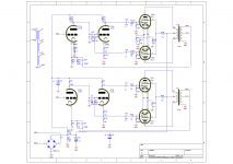
Yes a shared resistor for both output valves. A bit remiss of me to not include a schematic, but as I the OP was when I was at work, it was a bit tricky
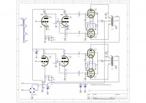
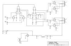
The first image is the schematic as provided by the seller. When I popped the lid off I noticed there was some significant differences so the second image is the original schematic modified. That got a bit messy I thought so I sketched out my own schematic, which are the last files.
Are there any gotchas or pitfalls I should look out for if I increase the G2 voltage by lowering the resistor value?
Cheers, Jacob
Yes a shared resistor for both output valves. A bit remiss of me to not include a schematic, but as I the OP was when I was at work, it was a bit tricky
The first image is the schematic as provided by the seller. When I popped the lid off I noticed there was some significant differences so the second image is the original schematic modified. That got a bit messy I thought so I sketched out my own schematic, which are the last files.
Are there any gotchas or pitfalls I should look out for if I increase the G2 voltage by lowering the resistor value?
Cheers, Jacob
Attachments
Last edited:
The only thing I am a bit dubious about is the 1nf cap on the OT. It looks like a bit of a sticking plaster to solve instability issues, but its only on one side so its introducing high frequency imbalalance which equates to higher distortion. In the original it looks like it should be across the whole primary of the OT. It looks like a poorly implemented zobel without the series resistance.
I would take it completely out to see what effect it has.
Yes you could restore the original 1K5 screen resistor, which should increase power output a little.
Shoog
I would take it completely out to see what effect it has.
Yes you could restore the original 1K5 screen resistor, which should increase power output a little.
Shoog
Hey Shoog,
argh, my bad I just noticed on review I posted an older image where I had the 1nf in the wrong place It is actually across the primary of the OT.
I've done quite a few mods to one of the amps I have and the other is stock as a comparison. They sound pretty good for how cheap they were!
Ok thanks I might try the 1k5 and see how it goes.
I've made resistor changes to the preamp stage to accomodate a 12AY7, and the phase splitter (inc switchable heater wiring) for a 6DJ8 or 12AY7. I've currently got adjustable GNFB feedback and I'm also experimenting with LED bias for the preamp. I like valve amps! (always had SS until 8 months ago).
There's lots of other changes I've made along the way as well, including some safety ones, for example who makes and sells and amp with the earth pin of the IEC socket connected to nothing??
cheers,
Jacob
argh, my bad I just noticed on review I posted an older image where I had the 1nf in the wrong place
It is actually across the primary of the OT.I've done quite a few mods to one of the amps I have and the other is stock as a comparison. They sound pretty good for how cheap they were!
Ok thanks I might try the 1k5 and see how it goes.
I've made resistor changes to the preamp stage to accomodate a 12AY7, and the phase splitter (inc switchable heater wiring) for a 6DJ8 or 12AY7. I've currently got adjustable GNFB feedback and I'm also experimenting with LED bias for the preamp. I like valve amps!
(always had SS until 8 months ago).There's lots of other changes I've made along the way as well, including some safety ones, for example who makes and sells and amp with the earth pin of the IEC socket connected to nothing??
cheers,
Jacob
Unbypassed shared cathode and screen resistors in a push-pull output may reduce even-order distortion by helping to force balance. They may increase odd-order distortion, via a re-entrant process. The even-order (mainly second) still happens and can be seen at the cathode/screen even though it cancels in the OPT. This even stuff then reacts again in the valve with the incoming signal to make more odd-order. Tghis extra odd-order may be inphase or antiphase to the odd-order already created by the valves, so it can add or subtract (but adding is more likely!). I guess it depends what you are trying to achieve, and how much global feedback there is. I'm not saying you should worry about this, but be aware of it.
Increasing g2 voltage will run the valves hotter, which will probably increase output and reduce valve lifetime, and may or may not change the distortion.
Increasing g2 voltage will run the valves hotter, which will probably increase output and reduce valve lifetime, and may or may not change the distortion.
Unbypassed shared cathode and screen resistors in a push-pull output may reduce even-order distortion by helping to force balance. They may increase odd-order distortion, via a re-entrant process. The even-order (mainly second) still happens and can be seen at the cathode/screen even though it cancels in the OPT. This even stuff then reacts again in the valve with the incoming signal to make more odd-order. Tghis extra odd-order may be inphase or antiphase to the odd-order already created by the valves, so it can add or subtract (but adding is more likely!). I guess it depends what you are trying to achieve, and how much global feedback there is. I'm not saying you should worry about this, but be aware of it.
Increasing g2 voltage will run the valves hotter, which will probably increase output and reduce valve lifetime, and may or may not change the distortion.
I would guess that the main class of operation would have a significant part to play in determining if a shared screen resistor raised the overall distortion. An amp designed to work predominently in class A would probably see a reduction in distortion, and one designed to be class AB might see an increase. This would be attributable to the asymetrical screen current draw on deep Class B operation.
Both of the designs I saw shared screen resistors on were plate to grid local feedback amps which my experience suggests are fairly immune to screen treatment anyway.
Shoog
Last edited:
I suspect the presence or absence of other feedback is a factor. If no other feedback is present then swapping some second for some third seems a bad deal, given that third probably sounds worse and second will already be reduced by the P-P anyway.
With extra feedback it might be better to reduce the second as much as possible, so that will reduce re-entrant distortion from the main loop. The NFB will reduce the third in the output stage anyway.
Somewhat different situation, but RF people have found that a tetrode/pentode power amplifier needs an extremely stiff g2 supply in order to reduce 3rd IM which would otherwise come from re-entrant distortion. No feedback, and not bothered about 2nd, so different from the audio case but the distortion mechanisms are exactly the same.
In my experience large resistors in series to G2 are not good in power stages. Modulation of G2 voltage causes increased distortion, especially intermodulation. This happens regardless of class A or class AB. Maybe a bit more in the latter.
I think that the higher distortion is caused primarily by the modulation of G2 voltage. It drops beacuse of the higher G2 current through that big resistor and mutual condunctance and internal impedance both change but not in a "combined linear way".
The best solution for me is a regulated power supply. I have always found lower distortion with regulated G2 supply and more importantly a better sound.
Last edited:
In my experience large resistors in series to G2 are not good in power stages. Modulation of G2 voltage causes increased distortion, especially intermodulation. This happens regardless of class A or class AB. Maybe a bit more in the latter.
I think that the higher distortion is caused primarily by the modulation of G2 voltage. It drops beacuse of the higher G2 current through that big resistor and mutual condunctance and internal impedance both change but not in a "combined linear way".
The best solution for me is a regulated power supply. I have always found lower distortion with regulated G2 supply and more importantly a better sound.
Have you tried, and are you specifically refering to a shared G2 resistor - as this is the only point of discussion here.
Br Cornelius
Have you tried, and are you specifically refering to a shared G2 resistor - as this is the only point of discussion here.
Br Cornelius
Yes, I have tried not with every valve though. I tried with EL84's, PCL82's and 6V6's.
I also tried something halfway, i.e. a shared small resistor + a number of 5W zener diodes in series to fairly regulate the G2 supply. This simple solution was already a good improvement. The 6V6 amp was basically class A, surely up to 7W (9W max Pout at the start of clipping). The choice of class A with reduced Pout was a consequence of the concertina splitter driving the 6V6's which doesn't work at its best with class AB output stages, IMHO.
Shared screen resistors on balanced input stages make a bit more sense, as signal levels will be low so distortion will be less of a problem. Sharing the resistor means a cap can be omitted, and a cap would not work down to DC anyway so subsonic IM might be lower with a shared resistor.
Exactly.6P15 is not an EL84. It is more like an EL83?
Very interesting stuff guys, much appreciated.
Strangely I note on the 6P15-EV datasheet (I have a set of these) that although the general "electrical characteristics" show 150V for G2, the absolute max rating is 330V. The Chinese 6P15s look a lot like the Russian ones but I have no idea about the spacing & thickness of the G2.
It does appear that they've chosen 10K resistors to be "safe" as on the PCB of the amp in one corner it has a list (printed in copper!) of suitable output valves (marked with a tick) and there's quite a few, so limiting G2 to around 250V means if people tube roll it wont smoke their new valves
I've bypassed the shared cathode resistors for the output valves, so it looks like it might be worthwhile trying lower screen resistors if the combination of unbypassed cathode & screen resistors might create a distortion modifying effect.
Just as a general question, does anyone see any glaring errors/issues with the design? I know it's not cutting edge but it seems to perform quite well, although I haven't used the scope to do any real measurements yet....
cheers, Jacob
Look at this Application Report for the 6BQ5 which is an EL84:
http://www.retrovox.com.au/STC6BQ5.pdf
See the last couple of graphs for Class AB1 push pull. The total screen current (two tubes) does not change much until you get to very high power output levels. That is because as the screen current on one tube of the push pull conducts more on one half cycle the other conducts less and then they swap for the other half cycle - so the TOTAL screen current from both tubes is fairly constant. The implication of that is that you can use a common screen resistor for both tubes and get almost screen regulator performance.
There is another interesting note amoungst the "fine print" of that report. It says use 10K grid stop resistors but goes on to say that in situations where grid current is likely, then a 100 Ohm anode stop resistor may be prefered. So for Class AB2 it seems we should be using anode stoppers in preference to grid stoppers.
Cheers,
Ian
- Status
- This old topic is closed. If you want to reopen this topic, contact a moderator using the "Report Post" button.
- Home
- Amplifiers
- Tubes / Valves
- Effect of lower G2, EL84 PP