The 6E6P-E tube has an element at pin eight that consists of a very fine wire that circles about three-quarters of the way around the internal structure of the tube. It is fastened in four places on the top and bottom micas but isn't connected to any other elements. There is a description in the second data sheet at this link but I can't read Russian.
''GSTube.com''. Tubes, sockets etc. Parameters and characteristics 6E6n-DP
Does anyone know what this does?
John
''GSTube.com''. Tubes, sockets etc. Parameters and characteristics 6E6n-DP
Does anyone know what this does?
John
"Проводящий слой внутренней поверхности баллона (Вывод 8) должен иметь отрицательный потенциал относительно катода. Обрыв цепи Вывод 8, а также приложение положительного относительно катода потенциала к проводящему слою приводят к выходу лампы из строя."
"The conductive layer (=screen) inside the tube (Pin 8) should have a slight negative potential in relation to the cathode. If Pin 8 is left open, or a positive potential in relation to the cathode is applied, it can cause a tube failure."
This means the usual way of dealing with such a screen. Simply apply ground potential. Due to the cathode resistor, the screen will be naturally a bit more positive than the cathode.
.. If Pin 8 is left open, or a positive potential in relation to the cathode is applied, it can cause a tube failure.
..Simply apply ground potential. Due to the cathode resistor, the screen will be naturally a bit more positive than the cathode.
doesn't this contradict ?
i've been always wondering about the function of that wire element.
i'm using diodes in cathode bias. it looks like if it needs to be even more negative than cathode, separate supply should be used (?)

To connect to the cathode.
http://lampilich.narod.ru/lamp_ru/pentodru/6e6p.html
http://lampilich.narod.ru/lamp_ru/pentodru/6e6p.html
Last edited:

It looks to me like a classic drawing of the shield around the tube.
However in looking a the 6E6P that I have , it is a single gold wire which forms a vertical loop around the outside of the plate. This loop is on the ends of the plate which are partially open box structure. The ends are along the axis of the grid and screen support rods.. The loop is offset from the axis of the cathode/grid/screen and thus is asymmetrical to the rest of the tube structure..
I have no idea what this is for.
Clarify what exactly?Could you explain that in engineering terms? I have no idea what that is.
See photos:
Around two cathode grid control and screen.
The anode is located at a great distance, so that tetrode depressed dynatron effect.
Gold wire is connected to pin 8 outwardly within the cylinder is connected to the coating of glass - it is a static screen.
Attachments
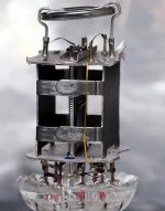
6Э6П tetrode tube with a spatial suppression dynatron effect. This optional wire promotes this.
thank you, finally some info on that. yet i have to learn about a dynatron effect, but i guess it's not relevant with audio frequencies, so it makes no difference if. it's tied to ground or cathode..
I really don't know, but would guess at some form of induction loop, aimed at working around some specific external sensitivity or influencing internal characterisctics via induction at uhf ??!?? But then then why connect it to a pin ?
Seems too small and strangely placed to influence conduction within the valve or do anything with secondary emission as a dynatron electrode ?
Seems too small and strangely placed to influence conduction within the valve or do anything with secondary emission as a dynatron electrode ?
Trying to piece together the puzzle....... perhaps it's a loop because it acts by induction, it's gold for skin effect conduction at uhf, and at or below cathode potential to minimise secondary ion emission - hence the link to poor lifetime unless at/below cathode potential ???
Yes.The loop is open ended, so no current flow and no induction. It bows out against the glass. Possible contact with a coating on the inside of the glass forming a shield?
- Home
- Amplifiers
- Tubes / Valves
- 6E6p-e Little Tiny Wire