Hi all!
I have a TSE with 300b tubes that hum for the first 2-5 min when i power it on.
I have discust this with you people here before..but it's time to take care of it now")
Today i use the 6,3v AC, make DC and regulate it with a AD1084 to 5V.
My plan is to do like this:
Will this work? Hopefully this will make it hum free..
Regards //Daniel
I have a TSE with 300b tubes that hum for the first 2-5 min when i power it on.
I have discust this with you people here before..but it's time to take care of it now
Today i use the 6,3v AC, make DC and regulate it with a AD1084 to 5V.
My plan is to do like this:
An externally hosted image should be here but it was not working when we last tested it.
Will this work? Hopefully this will make it hum free..
Regards //Daniel
Maybe.Will this work?
One side of 300Bs heater (thus cathode) are common. If this point is ground (negative bias on the grid), it will work.
IMHO 4700uF is too small. Try 15000uF - 1R -15000uF.Hopefully this will make it hum free..
If later does not disturb you, don't worry about it.hum for the first 2-5 min when i power it on.
One side of 300Bs heater (thus cathode) are common. If this point is ground (negative bias on the grid), it will work.
Correct. If using cathode bias, you need completely isolated transformer, bridge etc for each valve.
IMHO 4700uF is too small. Try 15000uF - 1R -15000uF.
If the constant current circuit does its job, then 4700uF is fine. Reducing the ripple further on the input side to the LM317 will make a tiny difference to the current regulation which should be all but inaudible.
You should not place large capacitance after the regulator / resistor since this could create stability issues and will prevent the regulator from properly controlling the current. You should not think of this as a CRC filter.
@Green77 - circuit says LM317 - text says AD1084. I could not find data on the latter to check the details. LM317 would be OK provided that it was a suitable package and suitably coupled to a heatsink.
Last edited:
Thanks for the replies!
I have fixed bias to the 300b.
My bad, i have ap1084 regulator today.
Regards. /Daniel
Fixed bias should be OK using a single transformer so long as one end of each filament goes to ground. AD1084 may be OK - I just had trouble to find a datasheet to check the resistor value for the current control.
I just found the data - the manufacturer's site was off-line earlier.
So the AD1084 is available in different versions. The circuit that you showed can work with the AD1084-ADJ part, but not with the AD1084-5.0. Which version of the AD1084 are you trying to use?
Since the AD1084 can pass high current it is important to get this right, or you could destroy the filaments in your tubes.
The circuit you have sketched is a current regulator using an adjustable regulator (317)
The resistor between the output and adjust pin on the regulator is in the incorrect location. It needs to be connected to the output pin, with the adjust pin connected on the other end. The resistor is sized to the so the current it will result in a 1.25V drop across the resistor. Obviously the current you need is what the 300B likes to see for a 5V filament, which is 1.2A, which results in a resistor value of 1.25/1.2 = 1.04 ohms
One other thing, you will need to plan for dropout voltage between 2.5 to 3 volts, in addition to the 1.25V drop across the resistor. This means your minimum DC voltage at the input pin of the regulator is 9VDC. Also plan on heatsinking the regulator, since it will be dissipating close to 4W. (3V x 1.2A)
David
The resistor between the output and adjust pin on the regulator is in the incorrect location. It needs to be connected to the output pin, with the adjust pin connected on the other end.
Ouch! I missed that. And I used to be a hardware designer. I must be losing it...

One other thing, you will need to plan for dropout voltage between 2.5 to 3 volts, in addition to the 1.25V drop across the resistor. This means your minimum DC voltage at the input pin of the regulator is 9VDC.
Yep. You can't generate 5 V from a 6 V AC transformer winding using a linear regulator.
At low mains, you'll have roughly 0.9*1.3*6 = 7 V on the input to the voltage regulator. That does not account for the ripple voltage. At 50 Hz mains, 1.25 A, 4700 uF, you'll end up with roughly ((1/(2*50)) * 1.25)/4700E-6 = 2.7 V ripple. That doesn't leave enough voltage across the regulator to regulate properly.
~Tom
If the constant current circuit does its job, then 4700uF is fine.
If you use DHT, this is not entirely true.
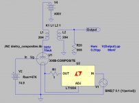
As Rod Coleman described (#26 pre amp topic), each injected mV hum more or less appears on the anode.
As you can see in my sketch, 200mVpp hum (BEFORE CCS!) produce 90mVpp output "noise".
In case of DHT not good enough filtration.
Attachments
If the constant current circuit does its job, then 4700uF is fine.
If you use DHT, this is not entirely true.
As Rod Coleman described (#26 pre amp topic), each injected mV hum more or less appears on the anode.
As you can see in my sketch, 200mVpp hum (BEFORE CCS!) produce 90mVpp output "noise".
In case of DHT not good enough filtration.
That suggests that the either the filament changes its resistance, or that the CCS does not do its job well enough, or a combination of the two. I don't doubt what you say, however. It would certainly be true that any hum component present on the filament would then appear as unwanted hum on the amplifier output.
What he needs to do is reconfigure the rectifier into a bridge so he is working with a 12V winding. That should provide enough voltage. It should work with if using fixed bias as pointed out above, although with a 2.5A rated transformer, he will be beyond the rated current. I would recommend adding another transformer with a full wave bridge, so there seperate heater circuits in case he wants to explore cathode bias, and heatsink the 317s (or 1034s) very well.
David
David
- Status
- This old topic is closed. If you want to reopen this topic, contact a moderator using the "Report Post" button.
- Home
- Amplifiers
- Tubes / Valves
- Will this work as a heater for 300b?