as far as the bias circutry goes, I switched back from the pos. ends of the bias batteries going to opposite tube cathodes to going to the same tube's cathodes, eliminating any neg feedback in the circut... I felt it didn't really help and might introduce artifacts from back emf getting introduced into the grid circuts from the speakers, especially since I will be seriesing about 26 8ohm speakers in proposed system...I've heard of a speaker repair company that can re-wind any speaker to a higher impedance.....at least 32 ohms, maybe higher...anyone out there know of a reputable place that will rewind voice coils of my EV-300 18"ers to 32 ohms or higher? If so please advise me of their email....a friend of mine says he has an old japanese stereo from the '60s with no output transformers and two 8", 500 ohm speakers !!! what the figbar ? Ive never heard of anything like that except of the early circlotron speakers from the 50's. Were they wound with resistance wire?.....thanks, midmoe
Last edited:
as far as the bias circutry goes, I switched back from the pos. ends of the bias batteries going to opposite tube cathodes to going to the same tube's cathodes, eliminating any neg feedback in the circut... I felt it didn't really help and might introduce artifacts from back emf getting introduced into the grid circuts from the speakers, especially since I will be seriesing about 26 8ohm speakers in proposed system...I've heard of a speaker repair company that can re-wind any speaker to a higher impedance.....at least 32 ohms, maybe higher...anyone out there know of a reputable place that will rewind voice coils of my EV-300 18"ers to 32 ohms or higher? If so please advise me of their email....a friend of mine says he has an old japanese stereo from the '60s with no output transformers and two 8", 500 ohm speakers !!! what the figbar ? Ive never heard of anything like that except of the early circlotron speakers from the 50's. Were they wound with resistance wire?.....thanks, midmoe
Very unlikely; there would be no advantage, and many disadvantages, to using resistance wire. (If one were in the game of making a "500 ohm speaker" simply by adding resistance for its own sake, one could more easily just use an external series resistor.)
Chris
attn: ralph at atmasphere...I have a schematic hard copy I can mail you if requested. The schematics on thread nos. 32 and 35 aren't finalized, not to mention hard to read. I still can't figure out how to load a short video, so for now stills is all I can muster....talked to you this am, thanks for your attention..please email me so I can get correct address. Thanks, midmoe
am under construction of a stereo version of the circlotron. Gave up on trying to keep the case size small and doubling up the tube count with "candleabras". Am using a double-wide chassis (16"X14"). Simply building two monoblocks in one case...the good part is that with some minor juggling, I can hook up all output tubes in series, with preamp tubes parrelleled, then hooked up in series with the outputs, leaving only a couple 68 ohmers across each preamp trio, to give 6.1 vdc on each tube instead of 6.3 by using a big diode in series, with appropriate crowbar and fuse prtection in case of main diode short or leakage. This will eliminate the bulky, hot fil. xfmrs. saving weight, increasing efficiency, and hopefully ridding the low level hum I think is field induced by the overburdened fil xfmrs. now....my friend brought up the wierd high imedance 8" speakers...only that they are 400 ohms, not 500...still, they look like conventional construction. the cones need repair and are generic, but looking foward to getting them hooked up just to see how they perform after a little work repairs from the holes chewed by mice, parelleling them should be a close match with amp impedance. I will be uploading a completed schematic of the stereo version, with latest updates and a built in meter/test panel, plus all 6 output tubes will be shown. A fellow in columbia has an HP distortion analyzer and can hopefully run the specs in a month or so.midmoe

newer stuff bias mod
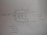
when first putting together the amp, I had the bias hooked up with ony one supply...not as complex as this schematic, but a rough equivalent. It seemed to work ok, but not taking any chances, as I still had instability problems (before freddie drive), I went ahead and hooked up the bias with two floating supplies of which I'm still using. I worked out this tentative drawing on paper only so far, as an idea to allow one supply to be able to bias both banks of outputs, with a common bias control, and a balance 10K pot even out the small variations, showing up at the output as a DC offset. It would seem to me that the inverting of the two 47Ks back to the respective grid supplies would allow some limited self-corrective behavior, allowing the balance control a less critical setting...comments?
when first putting together the amp, I had the bias hooked up with ony one supply...not as complex as this schematic, but a rough equivalent. It seemed to work ok, but not taking any chances, as I still had instability problems (before freddie drive), I went ahead and hooked up the bias with two floating supplies of which I'm still using. I worked out this tentative drawing on paper only so far, as an idea to allow one supply to be able to bias both banks of outputs, with a common bias control, and a balance 10K pot even out the small variations, showing up at the output as a DC offset. It would seem to me that the inverting of the two 47Ks back to the respective grid supplies would allow some limited self-corrective behavior, allowing the balance control a less critical setting...comments?
Last edited:
review
upon review, I can see now that my bias would be way too negative...but with a lower supply voltage, or perhaps even better, a higher value of resistors in series with the balance control, a correct range of -10 to -20 VDC could be attained with a common bias level contol, with center at the desired -15 VDC between each grid and cathode. This is only preliminary, and more of a question as to how to simplify design, eliminating the extra xfmr, upping efficiency, lower weight, and perhaps a beginning effort of minimizing output DC offsets. Perhaps even a couple transistors could be added into the network to amplify the corrective voltage feedback to allow a stable 0VDC at speaker terms under varying conditions....... midmoe
upon review, I can see now that my bias would be way too negative...but with a lower supply voltage, or perhaps even better, a higher value of resistors in series with the balance control, a correct range of -10 to -20 VDC could be attained with a common bias level contol, with center at the desired -15 VDC between each grid and cathode. This is only preliminary, and more of a question as to how to simplify design, eliminating the extra xfmr, upping efficiency, lower weight, and perhaps a beginning effort of minimizing output DC offsets. Perhaps even a couple transistors could be added into the network to amplify the corrective voltage feedback to allow a stable 0VDC at speaker terms under varying conditions....... midmoe
Thanks for a good read so far.
Did you try that bias circuit yet, and if so how did it go? I've been doing research towards building my own OTL amp to drive regular 8 Ohm speakers (I don't feel up to modifying my speakers). So far I've found a TV sweep tube that has the right ratio of plate resistance to gain to get the job done with only 4 tubes assuming circlotron topology. I've been doing reading to try to come up with the whole design on paper before making a single channel prototype(my end goal is a 4 channel amp), but I'm liking your approach of taking a design based on different output tubes and modifying it to work with what you have... So much so that I might stop racking my brain and give it a try.
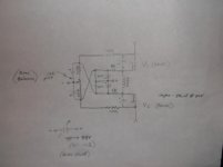
perhaps a better starting point for bias idea
Did you try that bias circuit yet, and if so how did it go? I've been doing research towards building my own OTL amp to drive regular 8 Ohm speakers (I don't feel up to modifying my speakers). So far I've found a TV sweep tube that has the right ratio of plate resistance to gain to get the job done with only 4 tubes assuming circlotron topology. I've been doing reading to try to come up with the whole design on paper before making a single channel prototype(my end goal is a 4 channel amp), but I'm liking your approach of taking a design based on different output tubes and modifying it to work with what you have... So much so that I might stop racking my brain and give it a try.
hello, I have adjusted the bias down to -8vdc, from -16vdc (with +150 plates) and get a very useable 40 wpc or so, and I have plenty to drive the 3 sets of bose 901s hooked up internally in series for 64 ohms, by using just the rear 8 speakers, then hooking up 3 sets in series also to give me 192 ohms per side, still a little low as I think I need one more set to add for 256 ohms per side total. It is good enough for now, still looking locally for one more set of 901s, series 2 to complete everything. It is clean 40 wpc, with no crossovers needed and reliable and stable with the auto-bias correction circuit I developed. Plus, no filament trans as the tubes are hooked up in series....I haven't been on DIY for months and have been spending my time on science forums site.....I tried hooking up a test monoblock with the 6AS7s with uneven results, so kept the stereo unit on the JJ brand 6550s and am very happy with them....edd ps, are you the atmasphere people who build the atmasphere amps up in wisconson?...If so, nice to talk to you on the phone earlier...and to electronic memory...yes the bias circuit works and I check the balance with the test panel and it is never more than a tenth of a volt off dead center....after nearly a year of use, and moving the unit from missouri to colorado....edd
Last edited:
Actually we built the amps in St. Paul, Minnesota.
You are the first I have seen to make 6550s work in an OTL, albeit with high impedance speakers. There are TV sweep tubes, like the PL509 or PL519, that can be operated such that the speaker can be 8 ohms and you can still make power.
You are the first I have seen to make 6550s work in an OTL, albeit with high impedance speakers. There are TV sweep tubes, like the PL509 or PL519, that can be operated such that the speaker can be 8 ohms and you can still make power.
hello, I have adjusted the bias down to -8vdc, from -16vdc (with +150 plates) and get a very useable 40 wpc or so, and I have plenty to drive the 3 sets of bose 901s hooked up internally in series for 64 ohms, by using just the rear 8 speakers, then hooking up 3 sets in series also to give me 192 ohms per side, still a little low as I think I need one more set to add for 256 ohms per side total.
Are you saying 40W into 192 ohms? That seems a bit remarkable. 40W would mean about 88V rms, and hence about 246V peak-to-peak. Can you really get such a large voltage swing with 150V power supplies?
Chris
not really sure, that is a guestimate based on current measurements per tube with a 6 output tubes per channel hookup. Plus I developed the floating inverted cathode drive, which adds some voltage swing, not much though, more for neg feedback within the driver to output stage. That got rid of instability in the stage, which I further enhanced with the neg feedback bias circuitry...The schematics may be on DIY, but better ones are on AK, along with a matching passive pre I designed (but with tone controls), but I haven't been on AK for months now...actually I think my overall (delivered)power output is on the lower end of my guestimate, as I am running the unit into 192 ohms, and (another guestimate) of 250 ohms is closer to the correct output imp. of the amp. This is why I am looking for another 901 series 2 system...then I figure I will be slightly over system requirements, at 256 ohms. As I recall, I was hoola on AK if interested......edd
thanks doug, and I went onto AK and I am on there with the same username of midmoe too, so a fairly complete schematic set is accessable. Of special meaning to me is the ICFRD or inverted cathodic floating reference drive....that turned a sort of odd but interesting basic circlotron design into a stable useful device...now if it were possible to have filament-less tubes, as the promise of diamond coated cathode tubes were once thought to be a technical reality, efficiency would be much closer to SS amp values. I use the amp as an auxillary room heater in the winter and sparingly in the summer...usually only about an hour per day....be careful of the 6AS7s, alot of them, including most of mine were chinese fakes and barely worked, having a tendency to short out and had horrible emmission although I did get one of the prototype monoblocks re-tubed to use them, the 6550s are reasonably priced and extremely reliable..although output impedance is higher, I like the bose 901s anyway, and since they are full range, no crossovers needed...plus a stack of bose 901s with the back 8 spkrs. facing you for a total of 24 speakers per side is an impressive sight. I take the grille cloths off for extra high end as the early cloths were too heavy and removing them adds quite a bit of brilliance that the 901s were criticized for not having....the surface area of all those closely spaced speakers adds up to a full range subwoofer...incredible bass even with the passive pre I built...be aware that the bose 901 series ones don't have the high end range of the series twos....I found that out as one of the systems in the stack is a series one, and has slightly different speakers, with black cones and square magnets, instead of the blue cones and round mags. and the sound is noticeably lacking in treble sensitivity and has an upper midrange peak at about 8Khz making them sound just a little harsh in comparison to the other two sets, which are both series 2s....edd
Last edited:
"filament-less tubes, as the promise of diamond coated cathode tubes...
Interesting. The 1st electro-fluorescent displays (1st gen VCRs) suffered mass failure until the cold cathode was used. Micro tips emitting what a hot filament wire would do. Funny, I use nickel doped, yellow made made diamond in nano tip manufacturing. They come in a 0.2mm thick sheet. This typical diamond coating could be ion machined to produce the nano lattice that you speak of for electron emission. The new cold cathode in the modern electro-florescent displays do use some sort (thorium?) of micro emitters. However very interesting topic, & off topic - sorry I admit.
My hoard 6AS7 are the real deal, RCA most of them from the late 50s.
I am excited to study your ICFRD (*Fred*)
Bose 901s, not bad. And they do have a bunch of high impedance paper tweeters. Never think I'd be thinking of working with a Z sub o this high!
Going to AK now.
Doug
- Status
- This old topic is closed. If you want to reopen this topic, contact a moderator using the "Report Post" button.
- Home
- Amplifiers
- Tubes / Valves
- medium power OTL circlotron amplifier