ketjie, again, thank you for the lovely drawing...I did notice that there were no 120 ohmers in series between the screens. (probably don't need them now anyway) Forgive my badly photographed, blurry pencil drawings. I shall upload power supply and short movie soon..... midmoe
Last edited:
chris each tube looks exacly as the brighness level as if in 6.3 vac setup.....regardless of what the meter says, if the fils glow just right, the voltage has got to be right. (each tube shows 10vdc on my vom meter)
Well, as I mentioned before, you won't necessarily get a very meaningful result from a simple measurement of voltage, for the chopped sinewave. However, if your voltmeter is a "traditional" one with an analogue mechanical meter, then on DC it is probably giving a reaonable representation of the time-average of the voltage. The voltage on one of the nominally 12.6V tubes will be a chopped sinewave with a peak amplitude of about 34V, and that time averages to about 10.8V, which is indeed roughly consistent with your measurement.
However, the rms voltage for the chopped sinewave comes out to about 17V, and this is what matters as far as the heating effect is concerned. So you are in fact running the tubes at the equivalent of roughly a 17V rms sinewave. This is considerably higher then the 12.6V they should be getting.
As said before, inserting the diode halves the power to each tube. If you shorted out the diode (not recommended, of course!), each of those tubes would be getting about 25V rms and therefore four times the proper power dissipation. Restoring the diode means the power dissipation is therefore instead twice what it should be. So they are definitely being considerably overrun.
Chris
chris. I would suggest you build a similiar lineup and see...it simple enough. I've been in electronics long enough to see a normally lit tube, from a distance of at least 25 feet. Now, whatever the meters or guides say, this thing sits here and looks fine to me. How can this be reconsiled? Seriously, build it and prove me wrong...I'd like that....midmoe
apparently I had my sunglasses on when conducting series string experiment...a thousand apologies...switching to regular prescriptions has proved I am wrong..midmoe
Glad to hear the law (of physics) is being upheld! Add another 25Z5 in your chain, and all should be just about right...
Chris
laws of physics are temporary approximations...25Z5 ? I am out of addl. 25Z5s, will chech this out. Probably will end up getting some nichrome wire from edmund scientific and build my own ballast "tube" as, ascetically I want only one more opening in the top. thanks. was thinking I might be "series strung up" in here when discovering when I had rushed back to the terminal to erase previous entry...and began deserved intellectual "woodshedding" as the little edit icon was gone. what about the whole voltage depth/ current depth thing? Am I again out of my "depth" ? transistorificationing some innocent tube?
laws of physics are temporary approximations...25Z5 ? I am out of addl. 25Z5s, will chech this out. Probably will end up getting some nichrome wire from edmund scientific and build my own ballast "tube" as, ascetically I want only one more opening in the top. thanks. was thinking I might be "series strung up" in here when discovering when I had rushed back to the terminal to erase previous entry...and began deserved intellectual "woodshedding" as the little edit icon was gone. what about the whole voltage depth/ current depth thing? Am I again out of my "depth" ? transistorificationing some innocent tube?
I'm not sure I'm catching all the nuances here...
Anyway, all you need is that a 120V rms sinewave becomes about an 84V rms chopped sinewave if you stick a diode rectifier in series. The rms voltage is what matters as far as heaters are concerned, regardless of the shape of the waveform. So a 12AU7, two 12BH7's, and two 25Z5's would, for example, be about right. Or anything else you care to string together (all the same current), as long as the total is about 84V.
Chris
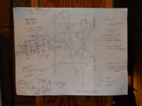
correction and revision
It's a bit hard to read the schematics you've posted. Is that a pinhole camera you are using?

no, just a pinhead cameraperson. Also failed to upload correctly short video...it seemed to go in alright, but should be here by now...wierd thing, when I was playing it back the sound went at speed, but video was on different time reference, maybe 1/3 speed.....was afraid something wasn't going work, as was first video upload attempt. I did the remake of the screen ckts...seems to have made no problems, but difference too small to detect by ear...creeping towards perfection... Plus I corrected a connection drawing problem in the grid of the lower, last, BH7....from first schematic...ketjie fixed it in her's.....the 14 megapixel camera I just bought took a pretty good video, if it ever gets there.....midmoe
am contemplating using series string on outputs of a stereo version...6.3 X 14 = 88.2 V......with the supply being 84.4 V, should leave comfortable margin on voltage to outputs. This will allow removal of bulky fil. xfmr, leaving room for a second, parrellel wired-in, 170V B+/B- mains xfmr.....and adding small fil. xfmr for driver tubes....as I figure it , each output fil would have 6.03 v....haven't tried this on the bench, so can make no declarative, table-thumping remarks yet.....midmoe
short video 001
An externally hosted image should be here but it was not working when we last tested it.
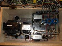
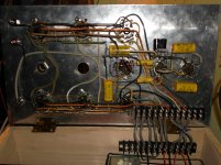
the prototype monoblock
Last edited:
stereo version losing appeal, voted down by asectics committe...did notice something kinda odd about the freddie drive. Was seeing if the 1K resistors could be elimenated, so shorted across them and got reduced gain, which I expected...but upon cranking up the preamp about 1db to compensate, noticed a reduction in the high end compared to before changes, so I left in the 1Ks. Tying the cathodes together would add neg feedback and lower impedance (as well as gain) in output stage, but why be frequency selective?
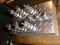
I finished second monoblock today, just as power failure stalled first play for an hour or so...I was down to kerosene heat and candles....quite some storm here in midwest. I changed the 82K in the phase inverter plate to grid ckt to 100K, giving a little extra gain, haven't gone in and balanced the phase inverter yet, but it must be pretty close, sounds fine. I'm sure the plate resistors need to be finessed to get a null output from the center of two matched 68Ks bridging the plates....I'm presuming this is the correct way to do this...tubes running not too hot and biases are very stable.....nice to get back to stereo after a week of mono only. As soon as snowdrifts go down a foot or so, will attempt to get local fab shop to cut logo out of aluminum tread plate..and someone has promised me to come in and finally load a short video correctly. Am still looking for two sets of earlier series bose 901s, anybody ? Don't care about equalizer, stands, cabinet appearance, and a few bad or missing drivers, ok. Will drive a reasonable distance within the missouri area to pick up. Thanks, midmoe
Iv'e been thinking about the balancing of the phase splitter....in the original grommes, the grounded grid has less gain so therefore needs a higher plate resistor....as compared to it's mate...since I've introduced so much NF into the mate, I had to switch resistor relationships. I was going to finesse the plate resists to null the bridge, but wouldn't a technically sweeter approach be to equalize the plate resistors, with say 56Ks and then adjust the grid-to-plate resistor, now at 100K (orig. 82K), to a point that brings null at my matched bridge center, placed across plates ? And wouldn't this keeping the gains of each side exactly equal keep them running in the same point of the tube parameters...?..and therfore minimize distortions? midmoe
Last edited:
equalizing plate resistors didn't work as hoped...I had to add pull-up (330K)from +250 to V1 top plate along with a 150K back to V2 plate(from V1 plate) to get a near balance, but then I'd lost so much neg feedback, overal gain was again too high. And then, using a variable resistor in place of the 150K, to attempt balance, the nul wasn't nearly as complete as with putting things back as they were. Any gains in plate resistances being equal (if any) were outweighed by attendant problems. As it stands, V2 top plate resistor is 56K and lower plate resistor is a 47K, bridged by a 220K in the new monoblock. The older one balanced out with a 150K across the 47K. This achieves a nearly silent nulls. Tom Petty never sounded so good. midmoe
- Status
- This old topic is closed. If you want to reopen this topic, contact a moderator using the "Report Post" button.
- Home
- Amplifiers
- Tubes / Valves
- medium power OTL circlotron amplifier