I will keep the ac for the 6550s and series the 3 driver tubes, so as to filter it down for dc, keeping load to fil xfmr to a minimum...Russel came down and took pic with his phone, but came out badly...so at this point, any one who wants a paper copy please email me at finite47@gmail.com and I will be happy to mail you one. Sorry about the delay. Russel also said he had trouble with triad tansformers running hot. Didn't know why, but I think it's because theyre not tuned to 60 hz. Will look for better xfmr. for companion monoblock. Of course the series string is coming off 120 ac input, not xfmr, so no problems with that....midmoe
Of course the series string is coming off 120 ac input, not xfmr, so no problems with that....midmoe
Understood...that's what I'm doing too. It works very well.
Chris
I haven't bothered with seriesing up the small tubes yet as I'm busy building companion model...but the formulae of 1/sqrt 2 is to multiply the 120v by .707 as I understand it. But isn't that the formulae for full wave rectification, not half-wave? Seems if you chopped the sinewave in half, you'd get less than the .707 figure....we will see. I will be needing 34 more 8 ohm bose 901 type drivers to build 2 columns of 26 series wired, each side 208 ohms. will have to check to see if theyre avail. from bose still. Last time I looked, only 1 ohms were avail. Anybody out there got extra 4" drivers from 901s lying around? Probably not too many people parting them out. The 16 ohm subs haven't shown to be a problem....got them on a 120 ohm resistor. Still can't believe how much energy shows up with such large resistance in the way. midmoe
I haven't bothered with seriesing up the small tubes yet as I'm busy building companion model...but the formulae of 1/sqrt 2 is to multiply the 120v by .707 as I understand it. But isn't that the formulae for full wave rectification, not half-wave? Seems if you chopped the sinewave in half, you'd get less than the .707 figure....we will see. midmoe
Chopping off the lower half of the sinewave means that the heaters in the chain will get exactly half the power they would otherwise have received, and thus the heating effect will be exactly the same as would be achieved by instead reducing the rms voltage of a pure sinewave by a factor 1/sqrt2.
In other words, the true rms voltage of the chopped-off sinewave will be exactly 1/sqrt2 of the rms voltage of the original sinewave. And it is this true rms voltage that should be, for example, 6.3V for the 6550 tube, since the power dissipation, and hence heating effect, is always, more or less by definition, V^2/R where V is the true rms voltage.
An ordinary ac voltmeter may very likely give an incorrect reading of the true rms voltage in the "chopped-off" case, since it is typically designed under the assumption that it is measuring a sinewave. A true rms meter, which is much more sophisticated and effectively carries out the process of squaring the instantaneous voltage, then time-averaging, and then square-rooting the result, would read correctly, and would give the correct 1/sqrt2 answer.
However, in this case where one is simply chopping off the lower half of the sinewave, it is elementary to see that the result of the squaring, time-averaging, and then square-rooting will be to give a value that is 1/sqrt2 of the answer for the full sinewave.
(Of course there should, strictly speaking, be a tiny correction to the above discussion becasue of the 0.7V forward voltage drop across the diode, but that is pretty insignificant when considering a 120V rms sinewave.)
Chris
as the circlotron nears final design completeness, I have used small variations from what is common knowledge available in literature, and seems trivial compared to the way I have the amp's output stage coupled to the driver stage. It seems the method of ground referencing the cathodes rails back to the driver's cathodes instead of to chassis ground through 1K resistors, may be unique and allows a real advancement in circlotron utility, with the only problem remaining, of having a a non-standard output impedance. If, indeed the coupling is unique and I am the first to come up with it, do I not have the right to name it? If I should be, then I call it the "inverted cathodic floating return drive". ICFRD or I see fred, or "freddie" for short. midmoe
chris, isn't what your'e saying is, with a single diode, power is .5 and voltage is .707 ? Since the tube fils. are dealing with power, should the math be oriented in a power requirement instead of voltage requirement? Also, I thought the foward voltage drop across a standard diode junction was .6v, not .7 I'm waiting for xfmrs. and tubes to come in. I'm running out of organ chassis' to scavenge for octal and 9 pin miniature sockets ( the old ones are so nice). Other than that, I should have another monoblock ready in no time. Are you building one too? I'm trying to "class-up" the next one's appearance, using aluminum tread plate on top for tube mountings. It's too thick and hard to punch, so I got special metal cutting hole saw blades that works great. The box is 8"X14" and 4" deep and hinged in a cigar box style. All power supply components are on the bottom of the inside, amp components under the top, only the tubes and input/output posts on the exposed alum. tread surface. This has worked out well for the prototype, giving easy access for alterations, so I think I'll continue to use this motif on any production units. These are the smallest dimensions for a reasonably uncramped assembly. I will get real camera today to phograph both the schematic and the amp itself. since the camera phone thing did't work out. My friend Ben is coming over later and perhaps we can figure out how to post. I did add a small muffin fan too cool the fil. xfmr, now I can keep the top closed when using for extended periods. midmoe
chris, isn't what your'e saying is, with a single diode, power is .5 and voltage is .707 ? Since the tube fils. are dealing with power, should the math be oriented in a power requirement instead of voltage requirement? Also, I thought the foward voltage drop across a standard diode junction was .6v, not .7 midmoe
Precisely. Suppose, for example, the filament string was operating at its correct voltage with the full wave supply. If a diode is now inserting in the chain, the power to the tube heaters drops to half of what it was. This means that the "effective" voltage to the heaters (i.e. the true rms voltage) must have dropped to 1/sqrt2 of what it was.
In other words, if a 120V rms sinewave is connected in series with a diode, the resulting output, with the bottom half chopped of, has a true rms voltage of 120/sqrt2 ~ 84.9V.
So a heater string connected to such a half-wave rectified sinewave would need the to be composed of tubes whose standard rms heater requirements
added up to 84.9V. (And, of course, all the same current draw.)
I think that whether the forward voltage drop is 0.7V or 0.6V is a fairly fine detail here.
Chris
Last edited:
I got tired of trying to find my misplaced camera, so I bought a new one today. I succeeded in getting the schematics for power supply and amp loaded onto my computer, and they are reasonably legible, but will need to call in help to get them to upload to this site. Please bear with me a little longer...if anyone could give me a consise tutorial on how to do this, it might speed things up....midmoe
BIAS SUPPLY MOD since each side's bias supply is referenced to it's respective cathodes, doesn't this introduce a small positive feedback in the bias supply system? I was thinking it might, and as an early concept was to squeeze in as much local neg feedback in as many places as possible, especially the output stages, so as to lessen parasitic tendencies and lower impedance...so I thought that swapping each bias supply's reference point to the opposite cathode rails might do the trick on addl. NF. It seems to have done so, as the volume seems just a little lower than before. Will have to dig up a double-pole double-throw non-shorting toggle to flip the references on the fly. Will go to radio shack to acquire the switch and visit my computer guy and try to get him out here to upload schematics, which are already in documents, and are fairly legible. I am also presuming at least several of you have already built my design as per my discriptions, and don't need the schematics, and have even come up with improvements of your own. Of course,I am especially intrested in output impedance estimations.....good luck. midmoe
went to town, got dpdt switch, hooked it up... no difference.....couldn't hear even a slight "click" during switchover, which is puzzling....I left the bias references in inverted mode as perhaps under full load and with a scope, some small improvement would be detected, or a miniscule drop in output impedance......with a repeated A/B comparison......midmoe
midmoe, to upload photos click the "Go Advanced" button below the message text box.
This will take you to a screen which has a box below for the button to "Attach Files".
This opens a dialogue box which allows you to browse your computer for the file (Photo), upload it, and attach it to your message.
This will take you to a screen which has a box below for the button to "Attach Files".
This opens a dialogue box which allows you to browse your computer for the file (Photo), upload it, and attach it to your message.
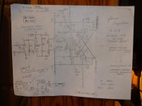
thanks to the gimp for the exxcellent info. Somehow the power supply didn't get included, but this is the intresting one anyway. Will work on getting power supply up later, also a short movie. The model number is 115 on the schematic, but numbered 9115 in text. This is because the basic design without output stage is a 115, but the entire amp has 9 tubes, hence the 9115 demarcation. I am planning on building higher tubed units, in stereo, using a similiar sized box, but "candle abra-ing" the output tubes. Instead of a single output tube per socket, an adapter will sit down and have room for 2, 3 or 4 tubes in each candleabra cluster. So the model number will reflect the 115 designation, preceded with the total number of tubes the power supply is designed to carry. A problem developed when I tried to order transformers for a second unit...seems as though the fil. xfmr. is no longer available from Allied, but they had a Hammond equiv. which I went ahead and ordered. Some of the higher tubes sets will be completely wired series string, controlled warmup. This will eliminate the bulky fil. xfmr. and allow room for a bigger power xfmr. for the main B+/B- supplies. After I've made four monos, I should be finished setting up a metal shop, and wood shop and have all the bugs worked out. I'm using 1/2" solid white oak for case sides, but local suppliers have walnut, cherry and ash. I'm using alot of old school parts, such as from 40-50s amps from organs for better quality than what is normally available. along with genuine catalin trim parts I have saved since th 90's midmoe
intresting "muntzian" development.....in fooling around with the series string in driver section, I placed the 12AU7 and two 12BH7s in series w/diode rectifier and put in as additional voltage drop a 25Z5 tube from the late 30's. Everything seems to be lighting up in a normal fashion. With a "ballast" tube mounted up on top, the heat will be discarded without having a hot resistor inside case. Of course, any 25 volt .3a tube might do....looking thru the tube manual, I see 25L6, 25N6, 25W4, along with a few others....if I can dig up a 25L6, I'll try it as that uses a standard octal socket. Funny thought...using the 25L6 as a headphone driver output....haha...or could some other 25 volt tube be used in some ancillary bias control circut...?...(dual purposed) or perhaps two 12 volters in series. this would widen the range of options in thinking out some sort of bias control/equalization circutry... madman muntz lives on...midmoe ps.....four sixes??
Well,finaly a cicuitdrawing 
To get a better view I redraw the thing.Can't say I like it

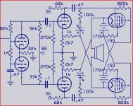
The screengrids are connected that the tube operate somewhat like a UL-PP with the tap at 50%.The voltage won't go very deep,poor swing not much output.Between the anodes is now 120+150+120+150=540ohm that comes as a load in parallel with the speaker.Another big loss.
Also you need 5 psu + the heaters.Not very economical.
Normaly a outputcircuit like this needs an input somewhat more then Vspeaker/2 ,allready rather lage, with this feedback to the cathodes you need even 2/3-th more.
Mona
To get a better view I redraw the thing.Can't say I like it
The screengrids are connected that the tube operate somewhat like a UL-PP with the tap at 50%.The voltage won't go very deep,poor swing not much output.Between the anodes is now 120+150+120+150=540ohm that comes as a load in parallel with the speaker.Another big loss.
Also you need 5 psu + the heaters.Not very economical.
Normaly a outputcircuit like this needs an input somewhat more then Vspeaker/2 ,allready rather lage, with this feedback to the cathodes you need even 2/3-th more.
Mona
Attachments
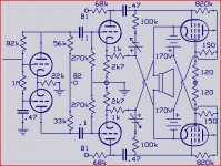
ketjie...thank you so much for the great, well thought out schematic....you do't like it or you don't like "it" ? I don't know if you built it and don't like the sound or don't like it from a design perspective ? As it has 6 output tubes instead of the shown 2, if you did build it I am hoping you made room for 4 more outputs......if... The screen criticism is valid, however. It is lossy, and needs cleaning up, but does the job for now and am using it on next monoblock......midmoe ps. sounds better than the mac.
Last edited:
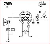
looking into the rca tube manual for likely 25 volt ballast tubes to use, I came across a 25B5, refered to as a "direct coupled power amplifier". It consists of two triodes with the grid of the first triode hooked up internally to the cathode of the second triode, with no external attachments ! I'm sure it somehow works, but am puzzled as to how the references to ground are missing to the oddball setup, with no way to set bias on usual places.....since the tube is dc coupled, it must use a staggered supply voltages, one side getting double the b+ than the other....sure seems strange to build a tube like that. It is an old-school 6 pinner, so maybe they would have hooked it up externaly, but ran out of pins.
...in fooling around with the series string in driver section, I placed the 12AU7 and two 12BH7s in series w/diode rectifier and put in as additional voltage drop a 25Z5 tube from the late 30's. Everything seems to be lighting up in a normal fashion.
If that series string is being fed from 120V, then you are considerably overrunning all the tube heaters. Each of the 12BH7 and the 12AU7 tubes will be getting almost 17V rms.
Chris
chris each tube looks exacly as the brighness level as if in 6.3 vac setup.....regardless of what the meter says, if the fils glow just right, the voltage has got to be right. (each tube shows 10vdc on my vom meter) Have left it hooked up in series and hour, turned it back on after cooldown, had very minor "surge" of 12AU7 fils.....within norms. Some of the smaller tubes surge a little anyway even with standard hookup. I do have to use a 100 ohms paralleling 12AU7, to equalize it's drop with others...looking back over the thread, I see I forgot to mention this...sorry. Right now , I have a 100 ohm, 5watt, which runs normal warm...so that is the only extra heat generated inside the case with the driver fils. This setup will remove 11.3 watts of power from fil. xfmr. now still a little hot even with muffin fan. With the outputs taking 60.48w, that should help alot with heating problem. ketjie...yes the voltage doesn't go deep as there is less room to travel with the lower B+ 170....however, I am going for current depth, not voltage. Essentially attempting to see how close a tube can made to behave as a transistor. I imagine the impedance is down about as far a possibe with 6 tubes....nearing 200 ohms with max. heating of the 1000 ohm, 10 watt rheostat with white noise taken as reasonable approximation. Yes the screen circut is lossy, have wired and rewired the prototype so many times, don't want to stress the sockets anymore, plus I'm using solid wires which can't take too much movement. The screens will be fixed this coming week. I put such a lossy matrix in to quiet the overshoots on large bass notes...this was before the "freddie drive" was in....I'm quite sure a change back to a more normal screen wiring can be made without blowback in next one. I got in all the tubes, xfmrs, caps and etc....should know by middle of next week how to fix that and other small issues.. the "tread" polished alumnum top looks cool, Almost a mirrored surface.....midmoe
- Status
- This old topic is closed. If you want to reopen this topic, contact a moderator using the "Report Post" button.
- Home
- Amplifiers
- Tubes / Valves
- medium power OTL circlotron amplifier