Keep the gate resistor 1k and replace the cathode resistor that sets the current with a 2k variable resistor and very carefully adjust it in the circuit. If that doesn't make it work then switch to a gyrator (just an extra couple of resistors and one capacitor) which will probably work better anyway.(Be careful adjusting that resistor with the high voltage present.)
I'm not familiar at all with the gyrator circuit. Do you know a good resource that will help me?
I'm going to replace the left channel CCS first, as the right channel seems to work fine.
Thank you.
I believe the grounding is OK.
OLG?
OLG?
How is grounding, local decoupling? Sounds very much like motorboating - the CCS raises the OLG compared to a resistor and voila.
Stop! Read the datasheet for the 10M45. You really need more current through the 10M45 for it to work well.
My datasheet says good for 2 - 100mA. I used the data sheet to calculate the correct resistor. I could not find on my data sheet where it says it needs more current to work well. I am interested in reading more about that. Do you have a link?
Thanks.
Stop! Read the datasheet for the 10M45. You really need more current through the 10M45 for it to work well.
+1
I disconnected the gNFB feedback loop today and voila, the CCS works fine.
I haven't had time to go any further. Since the right channel worked, and the left channel had the problem, I'm guessing that one of the output transformers had the blue & brown plate wires reversed from the factory.
I'll put it on the scope when I get a chance and verify that.
Thanks for all the help.
Scott
you still need to add a small resistor in series with the led and connect the gnfb resistor to that resistor.....
Yes Tony, that's how I built it originally. A 100R resistor in series with the LED and gnfb applied at that point.
Yes, that sure is shown as a 100R. That's what I'm using now. Thanks for the article.
Yes, I did use a heat sink. I'm not sure that it needs one at that current, but I erred on the side of safety anyway. I just cut a chunk off of an old CPU heat sink and tapped and threaded it. You can see them in this photo.
Don't be blinded by the LED bias circuit though!
Don't be blinded by the LED bias circuit though!
scott17,
I am thinking of using the current source in the same position as yours(the driving tube is a triode not a pentode like yours), do you use a heat sink on the 10M45? I am using about 2-3 mA though this IC and about 150V across it.
Attachments
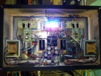
One more thing. Don't forget that the heat sink will have the B+ voltage on it. So be careful.
Since dissipation is small, no problem to isolate the device from heatsink with insulating washers.
Believe me, the temptation to touch a heatsink, is always stronger than our memory, and on your assembly would be a little dangerous.

Scott17,
Thanks for info and warning. From your cct diagram, is the 100ohm and 1kohm positions interchange, i.e. your current cct diagram is incorrect.
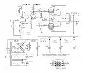
The drawing shown at post #20 is how it is now connected. 100R for the gate stopper, and 1K for the current set. The 1K is based on the calculation from the data sheet, and in my case it is correct and gives the correct voltage drop for my required current. The diagram is correct.
Last edited:
Since dissipation is small, no problem to isolate the device from heatsink with insulating washers.
Believe me, the temptation to touch a heatsink, is always stronger than our memory, and on your assembly would be a little dangerous.
Well, my memory must be better than yours then. I know not to touch it when it is on, and I can remember not to. Since I am the only one with access to it, it is perfectly safe and not dangerous at all.
Everything works now. It was a reversed OT primary. I know I should have checked that first, but since one channel worked and the other didn't, I suppose I overlooked it at first. My mistake. Never trust the color code or drawing. Sorry to waste so many folks time speculating since it was such an easy fix. Thanks very much.
Here is the schematic.
Here is the schematic.
Attachments
Everything works now. It was a reversed OT primary. I know I should have checked that first, but since one channel worked and the other didn't, I suppose I overlooked it at first. My mistake. Never trust the color code or drawing. Sorry to waste so many folks time speculating since it was such an easy fix. Thanks very much.
Here is the schematic.
Don't worry, can happen, Murphy lives...
The important thing is that you solved the problem.
- Status
- This old topic is closed. If you want to reopen this topic, contact a moderator using the "Report Post" button.
- Home
- Amplifiers
- Tubes / Valves
- 10M45S problem