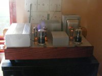
I am currently listening to the latest iteration of my DC7 amp concept. Its based originally on Gary Pimms Tabor amp.
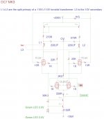
The latest version has a 12L8GT dual pentode at the front end driven by an input transformer and with a CCS under the tail of a LTP. The load resistor (22K) comes off the plate of the output tube and acts as the plate to plate feedback resistor.
This is direct coupled to a pair of EL86's. These have a grounded cathode for effective fixed bias, however the bias point is set by a combination of the drop over the 12L8GT load resistor and a current mirror feeding current through one side of the output transformer. This current mirror drives a 200uf cap before going into the output transformer. This makes the output self biasing and gives matched current on either side of the transformer for zero DC offset.
After a few trials getting the current mirror to work, it stable and indeed self biases. Remarkably one of the 12L8GT is quite unbalanced and it managed to adjust without issue.
Result - clean and detailed with tight bass. Its a bit zingy at the moment as I need to work a bit on load the input transformer. A subtle but nice step up from the DC7 MK2.
I will trace out the exact circuit when I tidy up the case a bit on the bench, but hopefully it will go into service soon.
Shoog
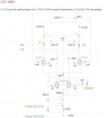
Some small revisions. Current balance on the current mirror load was rubbish until I moved the 270R resistors.
Output screen dropping resistor increase to reduce current in the ouput.
Correct loading of the input transformer.
Working great and sounding damn fine. Difficult to say exactly if it sounds better than the DC7 MK2 as the input transformer on that was slightly rolled off and so a lot of the changes could be just down to improved bandwidth. Overall gain is down on the MK2 version - which is due to the increased gain of the output stage forcing more feedback signal.
Shoog
Attachments
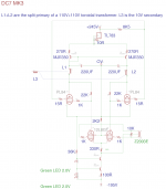
I suppose it was wishful think to expect that the output tubes would bias up to the right 50mA current as if by magic. After a few Red plate moments I realised that it would probably need a little help along the way so I went for the trust TL783 high voltage regulator to make a nice little 120mA CCS.
Everything now settles down nicely all by itself.
Shoog
Everything now settles down nicely all by itself.
Shoog
Attachments
I went back and modified my DC7 Mk 2 6AS7 amp to incorporate this "inverted Bias" arrangement. Once I got it working it sounds cleaner than the version with the cap to cap CCS bias arrangement it replaced. A nice improvement.
However the MK3 definiately sounds better than the modified Mk2. The top end is slightly more extended (probably due to the difference in input transformer), but the main difference is in the bass. The bass is significantly tighter and better defined. Overall this makes the amp sound much more refined. This just goes to show that in a plate to plate feedback arrangement all of the extra gain is been converted into lower output impedence and consequently better damping. Also the EL86 is definitately a very silky smooth sounding output valve which lives up to its sleeper tube reputation.
Its nice to see the concept evolve and get better as it does so, well worth all the effort.
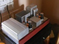
The only issue I have is that everything is in such a tight space in the DC7 MK3 that things run quite hot and this cannot be good for long term reliability. I may have to experiment with some forced air ventilation to keep temps down.
I will take some pictures of the new build as soon as I tidy up and spray the case and add a nice face plate.
Shoog
However the MK3 definiately sounds better than the modified Mk2. The top end is slightly more extended (probably due to the difference in input transformer), but the main difference is in the bass. The bass is significantly tighter and better defined. Overall this makes the amp sound much more refined. This just goes to show that in a plate to plate feedback arrangement all of the extra gain is been converted into lower output impedence and consequently better damping. Also the EL86 is definitately a very silky smooth sounding output valve which lives up to its sleeper tube reputation.
Its nice to see the concept evolve and get better as it does so, well worth all the effort.
The only issue I have is that everything is in such a tight space in the DC7 MK3 that things run quite hot and this cannot be good for long term reliability. I may have to experiment with some forced air ventilation to keep temps down.
I will take some pictures of the new build as soon as I tidy up and spray the case and add a nice face plate.
Shoog
Last edited:
more CCSs
Hi Shoog,
I have been following your progress with interest as you always have very practical ideas. I don't understand all the points of you amp and biasing arrangement but is the toroid OPT is being used in a sorta parafeed arrangement?
From reading Gary Pimm and Morgan Jones I wondered if you had considered a CCS on the cathodes of the ouput valves as well as the current mirror
on their anodes?
tim
Not really a parafeed arrangement since there is no cap blocking the DC pathway. The cap has been moved to the least objectionable place, right before the transformer and as part of the power supply. Splitting the primary and fixing the bias allows the arrangemnt to self adjust whilst ensuring perfect current balance in the output transformer. It achieves this by allowing unequal voltages to develop at the input to each side of the primary.Hi Shoog,
I have been following your progress with interest as you always have very practical ideas. I don't understand all the points of you amp and biasing arrangement but is the toroid OPT is being used in a sorta parafeed arrangement?
From reading Gary Pimm and Morgan Jones I wondered if you had considered a CCS on the cathodes of the ouput valves as well as the current mirror
on their anodes?
tim
In the DC7 Mk2 (search for that to look at the schematic) the CCS was indeed in the cathode of the output tubes - and it worked extremely well in that position - however it required a large cathode bypass cap to make it work. The objective of this iteration of the design was to see if I could eliminate that cap and whether there would be any benefit in doing so.
Shoog
no caps required
Hi Shoog,
I'm only a novice but John Swenson discussed a parafeed scheme that didn't need a blocking cap.
RE: Diff CCS schematic - John Swenson - MagneQuest/Peerless Forum
http://johnswenson1.home.comcast.net/~johnswenson1/stereo/DiffCCS.GIF
I'll look up your DC7 Mk2 posts.
regards
tim
Hi Shoog,
I'm only a novice but John Swenson discussed a parafeed scheme that didn't need a blocking cap.
RE: Diff CCS schematic - John Swenson - MagneQuest/Peerless Forum
http://johnswenson1.home.comcast.net/~johnswenson1/stereo/DiffCCS.GIF
I'll look up your DC7 Mk2 posts.
regards
tim
Hi Shoog,
I'm only a novice but John Swenson discussed a parafeed scheme that didn't need a blocking cap.
RE: Diff CCS schematic - John Swenson - MagneQuest/Peerless Forum
http://johnswenson1.home.comcast.net/~johnswenson1/stereo/DiffCCS.GIF
I'll look up your DC7 Mk2 posts.
regards
tim
Parafeed very specifically refers to the fact that there is a parallel feed of DC current and AC signal. What that gentleman is describing is a form of series feed where the DC is in series with the inductive element (the OT) which develops the output signal against its reactance. What he is infact describing is the arrangment used in the DC7 Mk2.
He is misusing his terms and causing confusion.
Shoog
I originally built this with CCS where the current mirror is, but the chip I used wasn't robust enough for this application and they fried. thats why I implemented the Current Mirror. Its working after a fashion but its not totally happy and this is because the current mirror isn't voltage compliant enough in this position to do what I need it to do (soak up bias differences). So I am going to replace them with CCS which are up to the job. I will try DN2540's or IXY10m90 - but unfortunately this will require a Mouser order which may take a week or two to sort out (I hate ordering parts). Meanwhile it will go back on the shelf.
I upped the g2 feed resistor to 10K to get it to 170V and added a 100uf bypass cap which seems to have tightened up the bass somewhat.
Will keep you all posted.
Shoog
I upped the g2 feed resistor to 10K to get it to 170V and added a 100uf bypass cap which seems to have tightened up the bass somewhat.
Will keep you all posted.
Shoog
Hi Shoog,
Thanks for sharing, interesting implementation! the first time I saw an output stage fed by a CCS and 'fixed bias' (grid negative to cathode) was by Richard Sears, and is described in detail here It is not just because it is different that I like it, but specially the concept of separating PS from amplifier with a high impedance. Richard Sears applies it to SE stages, but I (also) like PP more, so I am interested in the further progres of your work!
Erik
- Status
- This old topic is closed. If you want to reopen this topic, contact a moderator using the "Report Post" button.
- Home
- Amplifiers
- Tubes / Valves
- DC7 MK3 up and running.