Thanks Ale, Coleman set to 1.8V? or 1,62V starved?
I have two Coleman's filament regs for 4P1L, I set each one to 325mA?
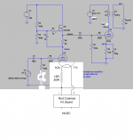
Ale that's the schematic that I want to use.
Hi Felipe,
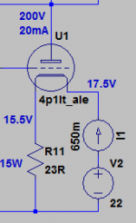
I will run the 4P1L driver at 210V/20mA with filament resistor of 25 ohms. Both 4P1L filaments sections in parallel so filament current is 650mA. Set Coleman regulator to 650mA.
Ale
I have two Coleman's filament regs for 4P1L, I set each one to 325mA?
Ale that's the schematic that I want to use.
Attachments
I have two Coleman's filament regs for 4P1L, I set each one to 325mA?
No, each regulator at 650mA.

Updated schematic, are correct the filament voltages?
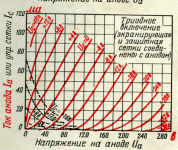
Please see the triode curves for 4P1L.
If you want to run 210V and 20mA then the effective bias must be more like 20V.
This means that at 650mA the filament bias resistor is about 30 ohms, and burns > 20W
This is really a bit too much power burn, considering the requirement of the stage.
I see no reason to run the 4P1L at high voltage in this position. Instead, I would suggest 140V 30mA for the 4P1L, so that you can use the 9V bias (650mA and ~14 ohm resistor). You will still get plenty of output swing with a CCS.
This will burn about 6W in the filament bias resistor - much more manageable!
Attachments
Hi Rod,
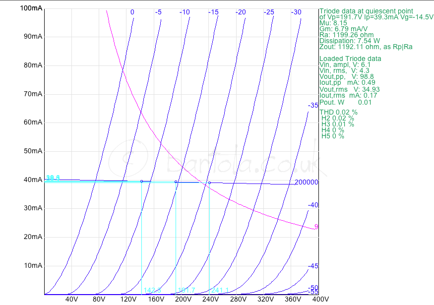
Yes, more manageable but with higher distortion, e.g. 0.03% @ 100Vpp, now if you look at biasing it on Vg=-15 V, Vak=190V (or Va0=175V with filament bias), Ia=40mA you get the minimum distortion of about 0.02% @100Vpp which is really good for a triode driver.
Rfilament has to be around 22 ohms / 15 W. That is the price you pay with filament bias though")
Ale
Yes, more manageable but with higher distortion, e.g. 0.03% @ 100Vpp, now if you look at biasing it on Vg=-15 V, Vak=190V (or Va0=175V with filament bias), Ia=40mA you get the minimum distortion of about 0.02% @100Vpp which is really good for a triode driver.
Rfilament has to be around 22 ohms / 15 W. That is the price you pay with filament bias though
Ale
I want to run the bias 180-210V 20mA, could you help to setup your filament regulator.I see no reason to run the 4P1L at high voltage in this position. Instead, I would suggest 140V 30mA for the 4P1L, so that you can use the 9V bias (650mA and ~14 ohm resistor). You will still get plenty of output swing with a CCS.
This will burn about 6W in the filament bias resistor - much more manageable!
TIA
Felipe
hi Felipe,
You can do this by using a 30 ohm filament bias resistor, which will develop about 20V across it.
But please be sure you can manage the power dissipation of the filament bias resistor (= 0,67 x Vbias or about 14W for your operating condition).
With the regulator, you need to make some changes, to handle the high voltage:
R8 = 10K.
The supply voltage needs to be about 5V above the output of the Regulator, ie
If Vbias = 20V, then Vout = 20 + 2,1V = 22,1V, and Vsupply = 27,5V; or between 26,5 and 29,5V
Last edited:
I don't mean to interfere, but this might be helpful to give an idea what to expect. According to the model Ale got from the 4P1L he measured this is roughly how things look. Of course, there will be variations from one tube to another in real life.
Yes, The variations from sample-to-sample are important, and probably quite wide with 4P1L. And if Ale's model says 17V where the Svetlana curves suggest 20V -we get an idea of the challenge!
Maybe it is best to buy a collection of 4P1Ls (well, they are cheap!) and matching up a few, and measuring the bias voltage required, before committing to a filament bias design.
Or then again, allowing the anode current/voltage a bit of variation in the design should not make too much difference to the sound. So if you bias to 17V, and allow 20 to 25mA to flow, for example.
I really think that we're not here in a situation where we have a lot of consistency across tubes, with a schematic which has been implemented by many and is tried and true. Obviously some experimentation is required.
To check the tube you got on hand and to experiment with the operating point:
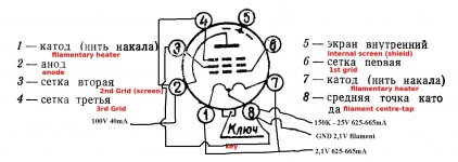
1) apply 2.1V DC to filament (+ on pins 1 and 7, and - on pin 8)
2) apply 25V DC through a 150K resistor, - to pin 6 (grid), and + on pin 8)
3) pin 3 should also be connected to pin 8
4) pin 4 (screen) should be connected to pin 2 (anode)
5) apply a variable HV supply, + to pin 2 (anode) and - to pin 8; start with 100V and measure the current through the tube; increase the voltage while monitoring the current until you get to desired plate voltage, perhaps 200V DC
6) adjust the voltage on the grid so that you get 20mA idle current
Make a note of all voltages, that's your operating point. Obviously you need two low voltage lab supplies to do this, and one high voltage lab supply.
If you don't understand what I said above and you need a schematic, then please don't do it, it is too dangerous.
To check the tube you got on hand and to experiment with the operating point:
1) apply 2.1V DC to filament (+ on pins 1 and 7, and - on pin 8)
2) apply 25V DC through a 150K resistor, - to pin 6 (grid), and + on pin 8)
3) pin 3 should also be connected to pin 8
4) pin 4 (screen) should be connected to pin 2 (anode)
5) apply a variable HV supply, + to pin 2 (anode) and - to pin 8; start with 100V and measure the current through the tube; increase the voltage while monitoring the current until you get to desired plate voltage, perhaps 200V DC
6) adjust the voltage on the grid so that you get 20mA idle current
Make a note of all voltages, that's your operating point. Obviously you need two low voltage lab supplies to do this, and one high voltage lab supply.
If you don't understand what I said above and you need a schematic, then please don't do it, it is too dangerous.
Yes, The variations from sample-to-sample are important, and probably quite wide with 4P1L. And if Ale's model says 17V where the Svetlana curves suggest 20V -we get an idea of the challenge!
Maybe it is best to buy a collection of 4P1Ls (well, they are cheap!) and matching up a few, and measuring the bias voltage required, before committing to a filament bias design.
Or then again, allowing the anode current/voltage a bit of variation in the design should not make too much difference to the sound. So if you bias to 17V, and allow 20 to 25mA to flow, for example.
DHT Data sheet voltages are referenced to centre point and for 4.2V filaments, I measured mine with one end referenced to ground and paralleled filaments at 2.1V so there is a 2V difference at least
If you wire it this way, so curves will be quite close...
Ale
I really think that we're not here in a situation where we have a lot of consistency across tubes, with a schematic which has been implemented by many and is tried and true. Obviously some experimentation is required.
To check the tube you got on hand and to experiment with the operating point:
1) apply 2.1V DC to filament (+ on pins 1 and 7, and - on pin 8)
2) apply 25V DC through a 150K resistor, - to pin 6 (grid), and + on pin 8)
3) pin 3 should also be connected to pin 8
4) pin 4 (screen) should be connected to pin 2 (anode)
5) apply a variable HV supply, + to pin 2 (anode) and - to pin 8; start with 100V and measure the current through the tube; increase the voltage while monitoring the current until you get to desired plate voltage, perhaps 200V DC
6) adjust the voltage on the grid so that you get 20mA idle current
Make a note of all voltages, that's your operating point. Obviously you need two low voltage lab supplies to do this, and one high voltage lab supply.
If you don't understand what I said above and you need a schematic, then please don't do it, it is too dangerous.
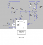
Iko could you check the jig?
Attachments
- Home
- Amplifiers
- Tubes / Valves
- The all DHT SET Headphone Amp