The spice model is not accurate in A2, so THD is not that representative.
You probably want to consider carefully to go down the DC coupled route with stacked supplies. I'm currently building a 4-65a SE in A2 which is proving to be very demanding due to the supplies.
Ale
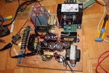
I think I know what you mean. I finally got over a psychological block and put together a prototype psu capable of about 750V DC at 2 x 100mA for my D3A-4E27 SE test project. All from spare parts that I had around, but seems good enough to test the amp with. From the sound of it I don't think I need to go A2. Anyway, it's off topic, so I'll stop.
Attachments
#1 3A5 (Mu-follower Gyrator DC coupled)-4P1l Parafeed Nickle or Amorphous Core OPT
Interested in seeing the Spice/schematic for this if you have one
Interested in seeing the Spice/schematic for this if you have one
I will start uploading some of the spice modelling.
I had a bit of a break thru today. Taking a spice model for the Hammond 5KSE and changing the model to work with 2x8 ohm secondaries. This matches a 32 ohm load. And it does so with significantly more power transfer and less distortion than any of the 32-38 ohm secondaries.
I highly recommend that balanced ouput is the way to go. big secondaries just make big distortion from all the secondary inductance and power loss from the voltage division with the secondary dcr. I would be comfortable with about any local transformer winder doing a double 8-10 ohm secondary while the large secondaries are only meant for nickle-core parafeed specialists IMHO.
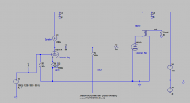
I'll leave you all for now with a "dream" schematic from back when good NOS DHT;s were "available". The 24 mu input DHT shown in this schematic is unobtanium as are the PX4's.
But I think a 4P1l cathode follower could drive a 1:4 stepup transformer-37A triode. Something to think about.
Attachments
Last edited:
I think that a DHT cathode follower is not a good idea in general. Filament current is too high for a typical interstage even if you use a 4P1L. If you want to provide some Kohms load it has to have inductance and the 1:4 ratio makes things a lot more complicated. You could try with one of those small DHP like 1S4, 1W4 which require 50 mA only or a parafeed drive.
A 3 stage amp without step-up interstage more likely will do better, IMHO.
A 3 stage amp without step-up interstage more likely will do better, IMHO.
I think that a DHT cathode follower is not a good idea in general. Filament current is too high for a typical interstage even if you use a 4P1L. If you want to provide some Kohms load it has to have inductance and the 1:4 ratio makes things a lot more complicated. You could try with one of those small DHP like 1S4, 1W4 which require 50 mA only or a parafeed drive.
A 3 stage amp without step-up interstage more likely will do better, IMHO.
Wouldn't you just create a center tap and pull the cathode current separate from the filament current?
Wouldn't you just create a center tap and pull the cathode current separate from the filament current?
I have never tried this. However if you use an indirectly heated triode (or pentode) it will not be different as the cathode follower has 100% local feedback and is a lot more linear than any DHT in common cathode configuration. A 6V6, for example, would be a very good choice.
Anyway I think that a 3-stage (for example 3A5 or 26 + 4P1L + 307A) amp without such interstage will be a lot easier to make.
I've been working with a spreadsheet for transformer modeling I found on this site in order to simulate the dual 8 ohm secondary/balanced output. There is a model for the big Hammond 5KSE, which has a nice low primary impedance. By using the balanced output from the two 8 oh secondaries we can get that 1.5W from a 4P1l. Its quite amazing and confirms what Bud had said we want a low primary impedance for an SE headphone OPT. Combine that with the much lower DCR of balanced oupt and we have two stage all DHT headphone as a real possibility including orthos.
The dual secondary balanced out really helps get us away from high distortion high dcr/inductance secondaries.
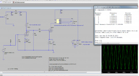
I've attached my spice simulation of a 4p1l to 4p1l dc coupled SSHV powered amp that looks to be a real step u from my high gm spud SET headamp. This shows surprisingly good sensitivity and exponentially better THD compared to my previous attempts.
As Pano said its time to start soldering. I have the coleman regs, #26 tubes, 4p1l's, and 307A's, and I know what to ask for from a transformer winder. This is somethig that could be done from most all transformer manufacturers, Bud, E-Print, Bartaluuci, Sowter, Edcore, Lundall depending on what you want and where you live it can be left to the discretion of the Builder. Just ask for low primary DCR, and dual 8 to 10 ohm secondaries. For high ohm headphones I think a parallel resistor is the way to go, from both a hum perspective and a cost perspective.
The dual secondary balanced out really helps get us away from high distortion high dcr/inductance secondaries.
I've attached my spice simulation of a 4p1l to 4p1l dc coupled SSHV powered amp that looks to be a real step u from my high gm spud SET headamp. This shows surprisingly good sensitivity and exponentially better THD compared to my previous attempts.
As Pano said its time to start soldering. I have the coleman regs, #26 tubes, 4p1l's, and 307A's, and I know what to ask for from a transformer winder. This is somethig that could be done from most all transformer manufacturers, Bud, E-Print, Bartaluuci, Sowter, Edcore, Lundall depending on what you want and where you live it can be left to the discretion of the Builder. Just ask for low primary DCR, and dual 8 to 10 ohm secondaries. For high ohm headphones I think a parallel resistor is the way to go, from both a hum perspective and a cost perspective.
Attachments
Maybe you used the 500uF capacitor on the output stage cathode bypass just for simulation. But if you don't go with stacked supplies and intend to use such a bypass, ouch! It's much easier to find a good quality small value coupling cap and go with ac coupling than to find a good quality large value capacitor.
Also, for the cathod bypass cap in the first stage you probably made a typo, because it is 1000F, not 1000uF.
Also, for the cathod bypass cap in the first stage you probably made a typo, because it is 1000F, not 1000uF.
Also, for the cathod bypass cap in the first stage you probably made a typo, because it is 1000F, not 1000uF.

Just ask for low primary DCR
That's a common mistake. You have to ask for lowest total DCR. This is achieved using half volume for the primary and half for the secondary.
If you ask for low primary DCR then a thicker wire will be used, typically, for the primary which will leave less space for the secondary and its DCR will be higher.
To compare the secondary DCR to the primary DCR you have to translate one of the two the other end (i.e. in a step-down OPT you multiply the secondary DCR by the square of the turn ratio and compare to the primary DCR or divide the primary DCR by the square of the turn ratio to compare to the secondary DCR).
In the case where you use half of the winding volume for the primary and half for the secondary you get the lowest total DCR (primary + secondary) and the lowest copper losses. It's mathematical! In practice you need to know how to do it. In addition there are further restrictions for wide-band high performance.
Agreed but its a touchy subject with transfo winders.That's a common mistake. You have to ask for lowest total DCR. This is achieved using half volume for the primary and half for the secondary.
.
Maybe you used the 500uF capacitor on the output stage cathode bypass just for simulation. But if you don't go with stacked supplies and intend to use such a bypass, ouch! It's much easier to find a good quality small value coupling cap and go with ac coupling than to find a good quality large value capacitor.
Also, for the cathod bypass cap in the first stage you probably made a typo, because it is 1000F, not 1000uF.
The text is hard to read but the first stage says it will be filament bias.
For the second stage I guess I just disagree, would rather have a quality electrolytic cathode bypass or large film cap and DC couple than ac couple to an output stage, coupling caps do bad things as the grid of an output tube nears zero. Also with the 4p1l we need as much transductance and gain as possible and we sacrifice both with filament bias in the output stage.
I guess I think stacked supplies look better in spice than in real life, adjusting it would be a nightmare. Prove me wrong and show me what the heck it would look like from the rectifier foward
It would be great if it worked but I just don't know?I'd be willing to try rod's fancy transister zener, but a big cap is a lot easier.
Last edited:
Not dht....
but this is what Audionote thought the Hifiman He-6 needed...
Audio Note Kits -HE-6 Headphone Amplifier
maybe this is why Regal wants so much power for his He-500's ?
dennis h
but this is what Audionote thought the Hifiman He-6 needed...
Audio Note Kits -HE-6 Headphone Amplifier
maybe this is why Regal wants so much power for his He-500's ?
dennis h
Not dht....
but this is what Audionote thought the Hifiman He-6 needed...
Audio Note Kits -HE-6 Headphone Amplifier
maybe this is why Regal wants so much power for his He-500's ?
dennis h
It's curious that AN should choose EL84s for this amp. A few years ago they were trying to apply 300Bs to just about everything - all the way up to multiple pairs for LP-cutter-head amplifier.
Noise could well be the problem for AN. They just did not 'get it' about filament heating - the Kit One used 7805-type regulators in voltage mode: about the worst-sounding technique possible - as well as too noisy for a headphone amp. By noisy, I mean broadband noise from the chip, as well as the completely inadequate rejection of high frequency noise from the mains & rectifiers.
Its funny you bring up the EL84, I've been doing "off-topic" simulations and a #26 or #4p1l driving an EL-34 triode is simulating better than any of the so called "linear" popular power DHT's.
Why?
Because the EL34 asks for a lot less driver gain.
Also I keep coming back to the fact that 1 Watt into 38 ohms is just as difficult as 4 watts into 8 ohms for an SET, for instance the 45 doesn't even stand a chance. The 4P1L can barely get there with the perfect parafeed tranny.
So I've sort of let this die as it really makes most since for my personal venture (already have a "low" power SET headphone amp" ) to use an EL84.
Of course the GM-70 or 4-65a beats everything by a huge margin but these would be tougher to keep quiet (black background.)
Last edited:
Its funny you bring up the EL84, I've been doing "off-topic" simulations and a #26 or #4p1l driving an EL-34 triode is simulating better than any of the so called "linear" popular power DHT's.
Why?
Because the EL34 asks for a lot less driver gain.
Also I keep coming back to the fact that 1 Watt into 38 ohms is just as difficult as 4 watts into 8 ohms for an SET, for instance the 45 doesn't even stand a chance. The 4P1L can barely get there with the perfect parafeed tranny.
So I've sort of let this die as it really makes most since for my personal venture (already have a "low" power SET headphone amp" ) to use an EL84.
Of course the GM-70 or 4-65a beats everything by a huge margin but these would be tougher to keep quiet (black background.)
EL34 triode is not too bad - but only if you use only a small fraction of its output power.
This is one of the situations where SPICE models can really lead us into deep woods.
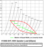
To illustrate the point, please see the characterisation of real tubes, made by Audiomatica (Audiomatica Srl). Their images are used with their kind permission.
I have compared the EL-34 and the 300B. The really obvious difference is the slumping & compression of the EL34 curves below 20mA. Note also that the mu is shifting at high voltages.
The comparison with 300B curves shows why the DHT is so much better.
My suspicion is that SPICE models do not adequately take account of these rather complex properties, leading us to think the EL34 is better than reality.
The only proper design method is old fashioned load lines, and real measurements of the tubes we plan to use.
Driver distortion for 300B can be tiny. See for instance the 6E5P driver in Shunt Cascode that Ale & I have already worked out: 0.23% distortion for 160V pkp-pk out.
Attachments
I see exacly what you mean about the EL34. I believe you are correct they couldn't find a filament regulation with black background with the 300B and chose this route. I asked our new USA AN distributor to quote the C-core transfo's shown and the reply was "we only sell those with the kit." Oh well.
I perhaps jumped the gun calling this the "all" DHT headphone amp thread, as this turns into a 3 stage amp, and if you're doing a 3 stage amp you might as well use a GM70 or other high voltage triode for optimal low distortion. This helps not only the crazy 5W ortho headphones but also the sensitive phones, Now if you don't need a full Watt of power for your headphones then a #26-4p1L SET is a fine choice..
I was reading a review of a commercial 6sn7/px4/300b headphone amp and spotted a picture of output transformers, they were Electraprints 5k:16 partial silver 40 mA. Interesting that the designer also chose not to go with a large secondary. If one thing came out of this thread I think this is most important, don't use a high dcr/inductance secondary. Either use a 16 ohm secondary or two 8 ohm for 32 ohm balanced drive.
As much as I like your Shunt cascode and agree it is the most practical means to achieve low distortion for this goal, I am afraid without a PCB I would surely be bitten with oscillation or some odd behavior not having a scope at home to debug, but I am allowing room in the chassis should a PCB come available.
So until then I will stick with the 307a/VT-225. I got such a good deal on these NOS tubes it would be a shame to not use them soon. I will start with a 417A ac coupled with a SSLV negative bias to the 307A triode (SSHV2 B+). I considered "stacked" supplies but this means I think a custom power transformer. I think this should be a good compromise.
I am calling it this the All WE High Power Headphone Amp since both tubes were made by Western Electric. Note I am using a coleman reg on the 417A indirect heated 417A because I have found not only much less measureable 60/120hz but also better sound using coleman regs on my 417 spud amp. This will also allow me to replace the driver wiith a DHT + Shunt cascode should a PCB become available. Also note this is a two chassis deal with absolutely no iron in the amplifier chassis beside the output transformers, and yeas they still need to be 90* from the power transformers. Headphone output transformers will pick up 50/60hz from power transformers over 3 ft away. The last thing is use a wiper on the gyrator in order to find the best spot, some 2H cancellation can be beneficial.
Attachments
Yes, you're right to worry about the ferrites, they are definitely needed, as with all high-gain HV stages.
Also, it's interesting that you have used Coleman Regulation on the IDHT driver - see what's on the PCBs, below.
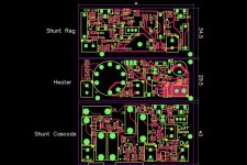
Since I like this Shunt Cascode solution so much, I decided to design the boards anyway, and a few days ago I sent out a Panel of PCBs for sample manufacturing. The picture is a sample of the Gerbers, also showing dimensions.
The boards are all 80mm wide (compared to the filament regs - 79mm wide).
The 3 designs:
- Shunt Regulator: 80mm x 34.5mm: A high-voltage Shunt Reg with discrete-transistor Error-amp for highest control of noise. Includes high-power CCS. Including completely adjustable reference voltage, temperature compensated.
- "Heater" a version of the Coleman filament Regulators, optimised for IDHTs, and configurable for Filament Bias. The IDHT B9 tube socket is on-board, and positions for cathode and grid resistors, and ferrite chip beads for the anode/g2 pins. It's configured for 6Ж9П-Е (6J9P-E) + E180F/E280F/E810F/EF80/EF184/6F23 - all of these are known-good for Shunt Cascode.
The on-board Filament Bias circuit allows low values of cathode resistor, with no bypass cap.
- Shunt Cascode PCB. holds the Darlington Shunt Cascode circuit, ferrite chip beads, high power CCS, and the servo circuit to allow dc-coupling of driver stage to DHT end-stage, with automatic biassing of the DHT.
The designs have liberal use of chip ferrite beads, to kill HF noise, parasitic oscillation etc. Together with the temperature compensation networks on all the CCSs, the circuit is somewhat complex, so I have laid it out in SMDs, which are standard build with me now. SMD layout keep the sizes of everything small, which is best for stability, and reduces EM noise pickup.
Like the Filament Regulators, the power transistors are on a board-edge, so that chassis can be used for heatsinking.
I hope to test them all out, and report some performance data soon.
Also, it's interesting that you have used Coleman Regulation on the IDHT driver - see what's on the PCBs, below.
Since I like this Shunt Cascode solution so much, I decided to design the boards anyway, and a few days ago I sent out a Panel of PCBs for sample manufacturing. The picture is a sample of the Gerbers, also showing dimensions.
The boards are all 80mm wide (compared to the filament regs - 79mm wide).
The 3 designs:
- Shunt Regulator: 80mm x 34.5mm: A high-voltage Shunt Reg with discrete-transistor Error-amp for highest control of noise. Includes high-power CCS. Including completely adjustable reference voltage, temperature compensated.
- "Heater" a version of the Coleman filament Regulators, optimised for IDHTs, and configurable for Filament Bias. The IDHT B9 tube socket is on-board, and positions for cathode and grid resistors, and ferrite chip beads for the anode/g2 pins. It's configured for 6Ж9П-Е (6J9P-E) + E180F/E280F/E810F/EF80/EF184/6F23 - all of these are known-good for Shunt Cascode.
The on-board Filament Bias circuit allows low values of cathode resistor, with no bypass cap.
- Shunt Cascode PCB. holds the Darlington Shunt Cascode circuit, ferrite chip beads, high power CCS, and the servo circuit to allow dc-coupling of driver stage to DHT end-stage, with automatic biassing of the DHT.
The designs have liberal use of chip ferrite beads, to kill HF noise, parasitic oscillation etc. Together with the temperature compensation networks on all the CCSs, the circuit is somewhat complex, so I have laid it out in SMDs, which are standard build with me now. SMD layout keep the sizes of everything small, which is best for stability, and reduces EM noise pickup.
Like the Filament Regulators, the power transistors are on a board-edge, so that chassis can be used for heatsinking.
I hope to test them all out, and report some performance data soon.
Attachments
That sounds great super idea to coleman reg/filament bias the input tube
But will the board be configurable to different output tubes?
Many would be fine with a 4p1L. I prefer the 307A over the 300B because it allows a high voltage swing at a lower current bias which helps in keeping the nudget and quality a bit in not needing the higher current handling transformer core that for the 300 B, it and I think the PX4 and even the 50 are a bit more suited to headphones for this reason. Not saying the 300B can't be a good solution its just a lot more expensive. And some will want the 2A3 due to its availability (the big JJ 2A3 has good higher voltage ranges that help with headphones also.)
Also not opposed to trying the 6J9P driver either, and having all the regs on one board would be awesome. Wish I could change the title of the thread to (The DHT Output Headphone Amp)
You do have a big challenge with the Shunt B+ reg, The SSHV2 is amazing in providing low output impedance transperant sound with a headphone amp.
But having all the SS on one board would be great, The best part is no coupling caps, no cathode bias caps. I really don't see the shunt cascode as being as "adding" a SS gain stage any more than using a gyrator or Cascode CCS's mu output.
I would defifnately be interested giving trying this, keep us posted.
- Home
- Amplifiers
- Tubes / Valves
- The all DHT SET Headphone Amp