Since this has turned into a search for the perfect transformer, I really don't have much to contribute. Guess I just get impatient will all the sims and talk, sorry. Too many threads turn into nothing more than talk. I want to solder stuff!
I don't think there is a lot to search for. Transformers with very low distortion for this application already exist and one doesn't need special cores. One just needs high quality transformers made with quality materials, including iron cores. If you have a look at transformers THD measurements inside the Gary Pimm site you will see that you don't need special cores even with very low signal (i.e. 0.01V primary voltage!). Above 100Hz the transformer THD is typically between -80dB and -120 dB! I don't think you will find a DHT that is able to match these numbers...
As mentioned before one has to be careful about the frequency range below 100Hz. Here primary inductance is a main factor to get low distortion. Namely the ratio XL/Req at the lowest frequency (30Hz is a good choice for SE) has to be as high as possible. A good compromise is a value between 6 and 8 for SE amps. XL =2*pi*f*L, Req is the equivalent resistance given by the source impedance in parallel to the load.
As I said I would choose a Lundahl or any other existing transformer that will perfectly match one application.
Problems arise when one wants "a full barrel and a drunk wife"!
Last edited:
Since this has turned into a search for the perfect transformer, I really don't have much to contribute. Guess I just get impatient will all the sims and talk, sorry. Too many threads turn into nothing more than talk. I want to solder stuff!
That's electronic engineering: 99% of time is pencil or display(s), 1% soldering. Also 90% of effort goes to bin, the other 10% creates the future.
Now back to business. The headphones of interest are in a rather tight Z range of 32~64Ω. The 300Ω (HD6x0) and (why in the world, but) 600Ω will get shunted to the nearest (64Ω) value. Any odd values, like 52Ω (HD380pro) will get a small series resistor to the same nearest value. The Z range of interest (32~64Ω) goes well with off-the-shelf LL1623. The 8Ω speaker gets the 3+3 secondaries paralleled, so total 6 out of 8 are used, same as headphones (6 for 32Ω and 38Ω, 7 for 52Ω, 8 for 64Ω). With all that, the primary Z stays in acceptable range (2500~3000Ω) with any load. The good thing in all this is automation: the commutation and shunting will be fully automatic, sensor-based. That is where my thoughts took me so far.
And a word about thinking out of the box. My personal project is wider than DHT headamp, but similar in the DHT part, and another part of it is a little illuminated button with a DHT triode sympol on it, which turns 'the magic' on. When it doesn't have to be on, or if I want zero THD+N, or for casual listening to save the DHT's life, or simply to fill the room with quiet background music, a simple and as close to perfect as possible PCM1794A-LME49990-LME49600 4W zero-capacitor-zero-inductor-signal-path headamp will extract precision sound from a tiny SD card with all my dear music on it. Perfection of form and perfection of essence in one (also perfectly constructed inside and out, Moth-style) device. There will also be some additional interesting parts in it. That's my music "box".
Last edited:
Some sophisticated thinking going on here, even if Pano gets antsy.
Were I to build another headphone amp that actually used M series core in place of capacitors to couple the 6922 long tailed cascode circuit to headphones, the phones would be EnABL'd. This would allow me to hear what M core does best. And by the way, Phillips Jan 6922 are so much better sounding than their commercial ken, the 6DJ8, that it is silly to use anything else.
Since the core quits transformation in any effective sense above 400 Hz, every thing else is antenna event, subject to dielectric materials as a control agent. I choose this to avoid the problem Per faces with amorphous core and others face with nickle core. A lack of internal gradient information in tones and transients. You will notice that all of Lundahls amopphous core coils have primary and secondary windings separate on the core. They must do this to avoid huge peaks in FR, just beyond the audible range.
Nickle, which functions to 3.5 kHZ for 48% and 10 kHZ for 80%, is also facing this problem, though you can have some interleaving. Mostly you have to quadfillar wind all primaries and secondaries,s to obtain enough losses in capacitive structure, which is not a single grouped event by any means though always portrayed as such for simple power transformers. This sort of arrangement does have a clearly characteristic sonic quality. A sweetness and also a comparative lack of internal structures to notes and transients.
Please note, these are not necessarily draw backs, for either type of material and how they must be used. Just a personal choice based upon your taste, that simple distortion measurements will not provide you enough information to make choices about. To wit, Gary Pimm's very clear presentation of distortion analysis between Dave's transformers and mine. Below 250 Hz his measure 20 db lower in distortion than mine. Gary uses mine in his amplifiers.
The reason is that mine have a huge amount of internal structure information. This because they have a huge amount of coupling surface Vs winding depth. Means that while I have higher measured capacitance, more of it is doing work as opposed to just laying around absorbing small signal information. I can also build in a dielectric circuit to emphasize this coupling. Since M3 rise time is equivalent to 80% nickle, I don't loose any leading edge information either.
Just my personal choice to solve the question of how to build a transformer that responds to nonlinear events with aplomb, balance and elegance. My peers provide equally good solutions, though aimed at expressing characteristics that are audibly different in availability, but very difficult to find in the grass of a plot of any kind, though wavelet analysis may change that to a degree.
Thanks Bas! I had not looked for Pieter's name, spelled correctly, before and was exhibiting my typical murican blindness to other territory's. I hope Pieter will forgive me.
Bud
We need an empiricist, once we nail down parafeed vs single feed we can get down to the nuts and bolts. I just don't want to repeat mistakes made with the OPT again (been "fooled twice now.)OK, not my cup of tea, so I'll leave you alone and get back to the 4P1L thread. I've already built, measured and listened to an all DHT-SE headphone amp. Not perfect, but at least real world stuff that tells me a lot.
The Z range of interest (32~64Ω) goes well with off-the-shelf LL1623. The 8Ω speaker gets the 3+3 secondaries paralleled, so total 6 out of 8 are used, same as headphones (6 for 32Ω and 38Ω, 7 for 52Ω, 8 for 64Ω). With all that, the primary Z stays in acceptable range (2500~3000Ω) with any load.
But Lundahls own datasheets recommend against 6 primarys as having too much insertion loss and 8 isn't even shown as a config. Seems that we lose the benefits of a C-core design by not folloing the "known" configs? Also I'm finding that a 5k primary works well with all the output tubes of interest from the 4P1l to the 300B.
Some sophisticated thinking going on here, even if Pano gets antsy.
Were I to build another headphone amp that actually used M series core in place of capacitors to couple the 6922 long tailed cascode circuit to headphones, the phones would be EnABL'd. This would allow me to hear what M core does best. And by the way, Phillips Jan 6922 are so much better sounding than their commercial ken, the 6DJ8, that it is silly to use anything else.
This is a much different headphone design. Where we are using a big powerful DHT to cruise along like a Mercede's SLR on I-70 intead of the Autobahn, gives better linearity and alows transformer coupling which I believe has a benefit over OTL and servoed SS.
Nickle, which functions to 3.5 kHZ for 48% and 10 kHZ for 80%, is also facing this problem, though you can have some interleaving. Mostly you have to quadfillar wind all primaries and secondaries,s to obtain enough losses in capacitive structure, which is not a single grouped event by any means though always portrayed as such for simple power transformers. This sort of arrangement does have a clearly characteristic sonic quality. A sweetness and also a comparative lack of internal structures to notes and transients.
This is where the decision is difficult. With a parafeed nickle design we don't have to worry about the secondary. A 1W 40 ohm secondary would work for about any phone.
My experience with single feed M-core transformers has been the transformer designer takes a 45 tube output transformer design and just makes the 8 ohm secondary 4x as long. This doesn't work. I ended up with a pair of transformers that literally cut my design power in half due to the voltage loss on the secondary DCR and the difficult inductive load.
Is it possible to start from the ratio instead of the core/primary when designing an OPT for headphones? I mean we need an OPT with 11:1 ratio instead of 25:1, this should be an advantage instead of being a disadvantage?
Bud, any insight on this one would be appreciated.
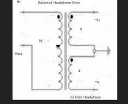
The other thing we are struggling with is "balanced" drive (see attached). It may be easier to spec a 5k transformer to have two 8 ohm secondaries which I've been told would impedance match with a 32 ohm headphone. I haven't been able to get this to simulate with LTSpice, do you have any thoughts on this or know the math behind it?
Attachments
Last edited:
A brief relief from transformer troubles:
Regal, what do you think about LCD2? Better, worse, same as HE-500? Looks much better made, costs a bit more, the same orthoplanar principle. Important difference is efficiency 91 dB/mW and Z=60Ω, which with LL1623 with all secondaries in series makes reflected Z=2693Ω -- right in the middle of 2500~3000Ω range.
Regal, what do you think about LCD2? Better, worse, same as HE-500? Looks much better made, costs a bit more, the same orthoplanar principle. Important difference is efficiency 91 dB/mW and Z=60Ω, which with LL1623 with all secondaries in series makes reflected Z=2693Ω -- right in the middle of 2500~3000Ω range.
My experience with single feed M-core transformers has been the transformer designer takes a 45 tube output transformer design and just makes the 8 ohm secondary 4x as long. This doesn't work. I ended up with a pair of transformers that literally cut my design power in half due to the voltage loss on the secondary DCR and the difficult inductive load.
I don't think the secondary DCR is the problem because on one side it becomes 4 times higher but on the other side the turn ratio is 4 times lower. From the point of view of transformer efficiency at low frequency nothing changes. The problem lies in the combination you make with those secondaries because from the point of view of AC losses they are not the same! That's why the layout for secondaries connections has to be a precise one. You have to connect the terminations in a precise order. If you do an apparently identical combination the result will not be the same. This happens mainly because the interface capacitances between a secondaries and a primaries are the dominant stray capacitances and obviously depend on the surface they share which is not the same going from the start of the winding to end.
A brief relief from transformer troubles:
Regal, what do you think about LCD2? Better, worse, same as HE-500? Looks much better made, costs a bit more, the same orthoplanar principle. Important difference is efficiency 91 dB/mW and Z=60Ω, which with LL1623 with all secondaries in series makes reflected Z=2693Ω -- right in the middle of 2500~3000Ω range.
This is true but I am bit smitten with the Hifiman midrange sound its really nice. Would like a design that can handle both brands. A good design (tube/topology/transfo) that delivers 1W at 40 ohm secondary should have no problem with the Audez phones (no need for a special 60 ohm tap.) I am by no means "ruling" out the LL1623 just want to explore my options.
I don't think the secondary DCR is the problem because on one side it becomes 4 times higher but on the other side the turn ratio is 4 times lower. From the point of view of transformer efficiency at low frequency nothing changes. The problem lies in the combination you make with those secondaries because from the point of view of AC losses they are not the same! That's why the layout for secondaries connections has to be a precise one. You have to connect the terminations in a precise order. If you do an apparently identical combination the result will not be the same. This happens mainly because the interface capacitances between a secondaries and a primaries are the dominant stray capacitances and obviously depend on the surface they share which is not the same going from the start of the winding to end.
It depends on who makes your transfo, my builder just quadrupled the secondary left the primary/core the same as for a 45 and I got a "nice" 10 ohm DCR secondary, the tota efficiency of the transfo gave about 50% less power than an "ideal" model, this is what I am "warning" folks about. Most transfo winders have a formula that is based on a 25:1 primary/core size and a headphone secondary is just considered a low quality "add-on." Rather than an opportunity to take advantage of the 11:1 ratio.
So hence my interest in the dual 8 ohm secondary "balanced out headphone drive" idea/rumor. Trafo builders have years of experience with 5k:8 transformers.
Regal,
As a thumbnail, secondaries can be doubled by multiplying them or dividing them by 4. So, 4 X 8 = 32, whereas 2X 16 does not equal 32. So a dual 8 ohm secondary will provide 32 ohms of load impedance reflection into the primary and into the plate. If you want to understand the formula, here it is in text, since I know from nothing about math notation from a keyboard in Windows.
5000 ohms primary load impedance. To find the turns ratio divide 5000 by the averaged impedance wanted and derive the square root of that. This is your turns ratio. For secondary turns in a SE OPT it is divided into the primary winding turns. For push pull it is both halves of the primary.
As for your concerns with your current transformer. Loses are not defined by the secondary alone. To get within a few % of the total power loss you must take the square root of the turns ratio and multiply the primary DCR by that, and, add it to the secondary DCR to approximate the infinitely reflected losses between the two. There is a core loss but it is insignificant enough to be ignored in a properly designed transformer.
In a general sense any SE OPT with more than 100 ohms primary DCR is going to have a high insertion loss. A 50% loss is pretty ridiculous, but 45 tubes require a fairly high inductance and with their desired current flow and the resultant gaps, you are stuck with either high DCR, a large (14 pounds 3.75" X 4.55" core perimeter) M core transformer, an amorphous core or a nickle C Core transformer, to generate the required inductance. Much better to accept a bit of flavoring and use a lower mu tube, like the 300B or 2A3.
Even with a lower mu tube you are better off with big than little, it just looks silly. What you will end up with is a SE DHT amplifier with an input transformer that you can switch from 1:1 to 4:1 or even 8:1 to get the gain down. If you can afford him Pieter's are the best in the world.
This does imply a possible push pull driver stage, with the inherent benefits of lower noise and distortion. A balanced out put that you could parallel for speakers or series for headphones begins to make a lot of sense.
I have found that DHT's actually require a good bit of current capability from their driver circuits. Paralleled driver tubes works. In my upcoming build I plan to use the very new lateral Fets, not Mosfets, on carbide substrate, in push pull config, with two stages to generate ~3 watts to drive a SE 300 B. The most linear load line for a 300 B is found at 4.545 kZ, by the way. A 2A3 will work the same from 3K to 7 kZ load line. The 45 is very particular and 10k is it's ideal. This implies a voltage and current, at zero signal level, that matches the load line. Once AC swing is applied, all load line / impedance matching is out the window anyway and the only important characteristic is how linear the voltage change is across the tube curve chart / real life.
Bud
Last edited:
I'm sure he will. I spelled his name in the german version years ago. And he still replies to my mails.Thanks Bas! I had not looked for Pieter's name, spelled correctly, before and was exhibiting my typical murican blindness to other territory's. I hope Pieter will forgive me.
Bud
It depends on who makes your transfo, my builder just quadrupled the secondary left the primary/core the same as for a 45 and I got a "nice" 10 ohm DCR secondary, the tota efficiency of the transfo gave about 50% less power than an "ideal" model, this is what I am "warning" folks about. Most transfo winders have a formula that is based on a 25:1 primary/core size and a headphone secondary is just considered a low quality "add-on." Rather than an opportunity to take advantage of the 11:1 ratio.
So hence my interest in the dual 8 ohm secondary "balanced out headphone drive" idea/rumor. Trafo builders have years of experience with 5k:8 transformers.
It depends on how one makes it. If one has just a formula for a specific combination then he is not very much in control.... Anyway you really don't need a University degree to optimize the windings to get a balanced and efficient transformer! The maths is simple. It is more about practical experience.
If you had considerably less efficiency then it had not been properly "re-calculated" but this has nothing to do with the fact that one needs a lower turn ratio for higher load. In principle a turn ratio of 11:1 has no advantage on 25:1 if the primary impedance has to be the same. Actually can be worse! The very good choice of wire gauge is such that you can practically get identical results without changing the primary in most cases.
Last edited:
Regal,
As for your concerns with your current transformer. Loses are not defined by the secondary alone. To get within a few % of the total power loss you must take the square root of the turns ratio and multiply the primary DCR by that, and, add it to the secondary DCR to approximate the infinitely reflected losses between the two. There is a core loss but it is insignificant enough to be ignored in a properly designed transformer.
In a general sense any SE OPT with more than 100 ohms primary DCR is going to have a high insertion loss. A 50% loss is pretty ridiculous, but 45 tubes require a fairly high inductance and with their desired current flow and the resultant gaps, you are stuck with either high DCR, a large (14 pounds 3.75" X 4.55" core perimeter) M core transformer, an amorphous core or a nickle C Core transformer, to generate the required inductance. Much better to accept a bit of flavoring and use a lower mu tube, like the 300B or 2A3.
Bud
If you had considerably less efficiency then it had not been properly "re-calculated" but this has nothing to do with the fact that one needs a lower turn ratio for higher load. In principle a turn ratio of 11:1 has no advantage on 25:1 if the primary impedance has to be the same. Actually can be worse! The very good choice of wire gauge is such that you can practically get identical results without changing the primary in most cases.
I think we finally have gotten to the heart of the matter and why I have held off a design. With a 4P1L single-feed output odds are an 11:1 (5k:32) transfo is going to give the same power delivery as a 25:1, because unless we find a transformer winder willing to design from scratch the primaries on both will be the same, and hence the 50% loss of power I experienced.
So how do to proceed? I think we have two general choices at this point that make since:
#1 3A5 (Mu-follower Gyrator DC coupled)-4P1l Parafeed Nickle or Amorphous Core OPT
#2 ECC40 - 307A (or 2A3) Single Feed Mcore OPT (Balanced output 8+8 secondaries)
I would chose a 841/VT-51 with a gyrator mu follower for #2 but I am finding this tube very difficult to source. Of course there are variations on the two ideas, but basically we have #1 a smart 1W amplifer and #2 a fun 2W amplifier.
Regal, the transformer you need already exists. It is the Lundahl LL1627.
Primaries will always be all in series regardless of the load. Secondaries will be in configuration C for a turn ratio of 11.3 (i.e. 4.1-4.6K for 32-36 ohm), configuration D for a turn ratio of 8.5 (i.e. 4.6K for 64 ohm) and configuration F for a turn ratio of 4.25 (i.e. 5.4K for 300 ohm). You always use all secondaries and power loss is very low in all cases around 0.1 dB! The only thing you need to specify is the gap for a lower operative DC current. If you ask for 40-50 mA rather than the standard 90 mA, you will get the right inductance for 4-5K (i.e. about 25-30 H).
You could think about some way to swap terminations around (for example using jumpers or similar stuff) until you don;t find the right set-up and headphone so that you don't have to solder every time you change headphone. You could also ask for the best core they have (thin lamination) or the amorphous.
Last edited:
Regal, the transformer you need already exists. It is the Lundahl LL1627.
Primaries will always be all in series regardless of the load. Secondaries will be in configuration C for a turn ratio of 11.3 (i.e. 4.1-4.6K for 32-36 ohm), configuration D for a turn ratio of 8.5 (i.e. 4.6K for 64 ohm) and configuration F for a turn ratio of 4.25 (i.e. 5.4K for 300 ohm). You always use all secondaries and power loss is very low in all cases around 0.1 dB! The only thing you need to specify is the gap for a lower operative DC current. If you ask for 40-50 mA rather than the standard 90 mA, you will get the right inductance for 4-5K (i.e. about 25-30 H).
You could think about some way to swap terminations around (for example using jumpers or similar stuff) until you don;t find the right set-up and headphone so that you don't have to solder every time you change headphone. You could also ask for the best core they have (thin lamination) or the amorphous.
I agree this would be a good off the shelf choice. And I think the dual 8 ohm secondaries opens things up for Electra-Print and Ecore transformers which are a good value for custom stuff.
But I am with Pano we have options know and have gotten to the root-cause of the transfo issues so I am very enthused that there is some resolution to the transormer issue.
Time to start buildig stuff.
We basically have narrowed it down to two types of amplifiers: 1. low output all DHT 4p1l output 2 stge amp, and 2. high power 2A3/307A output ( will need to be three stage amp fo all DHT.)
We really have to watch sensitivity. the 3A5-4P1L is a good setup for an all DHT SET headamp. The plates would be paralell, gyrator loaded DC coupled to the 4P1l so as to allow positive grid drive. Its probably the only true 2 stage all DHT design we have with more power than a 6c45pi or 6EM7 spud SET.
Does anyone have experience with the 841 DHT, gain of 30 ?
I found a nice set of NOS 307A's for cheap so they are still available from the usual places The 4P1L & even 2A3 don't give a much advantage in power over a 6E5P or similiar spud amp, it doesn't make a lot of since to drive them with a super tube/pentode that would pump out 2 watts on its own either.
But the 307A gives more power and it is a fairly sensitive tube.
To keep it all DHT the only way would be a three stage amp.
An input tube like a 30, 01A, #26. Then an "output" stage consisting of a gyrator mu out 4p1l dc coupled to the 307A. I am having a mental block on what "stacked" supplied SSHV's would look like. This would make a nice all DHT headphone amp/5W speaker amp. Does anyone have a schematic of what a "stacked" pair of SSHV's looks like included the rectifiers/prefiltering?
Yes I hope Ale doesn't mind me posting this. I can work it up for a 26-4P1l-307A, but I will need help with the stacked power supplies.
I personally would lean to a 30 input simply because it is easier to deal and less microphonic from what I understand, But I have #26 and 4P1l's on hand and no 30's so I guess it would be worth it to figure out the microphonics.
I see the amp being built with the #26 and 307A on top and the ugly 4p1l hidden underneath 4 Clean watts class A should be very easy for this amp, probably 5-6w with A2.
Also as I lost Iko with my spice THD #'s and I wanted to mention that Spice is predicting much higher THD that Ale has been measuring even as OTL preamp. I look at LT spice as a great tool for setting operating points determining zero grid thresholds, power levels, etc but think the THD isn't accurate because its based on an infinite low noise floor, the THD predicted from spice is good for relative comparison and little else.
I personally would lean to a 30 input simply because it is easier to deal and less microphonic from what I understand, But I have #26 and 4P1l's on hand and no 30's so I guess it would be worth it to figure out the microphonics.
I see the amp being built with the #26 and 307A on top and the ugly 4p1l hidden underneath
4 Clean watts class A should be very easy for this amp, probably 5-6w with A2.Also as I lost Iko with my spice THD #'s and I wanted to mention that Spice is predicting much higher THD that Ale has been measuring even as OTL preamp. I look at LT spice as a great tool for setting operating points determining zero grid thresholds, power levels, etc but think the THD isn't accurate because its based on an infinite low noise floor, the THD predicted from spice is good for relative comparison and little else.
Attachments
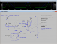
The spice model is not accurate in A2, so THD is not that representative.
You probably want to consider carefully to go down the DC coupled route with stacked supplies. I'm currently building a 4-65a SE in A2 which is proving to be very demanding due to the supplies. Not sure whether is worth the effort (and size and cost) for a headphone amp.
BTW: 30 is more microphonic than 26
cheers
Ale
Yes I hope Ale doesn't mind me posting this. I can work it up for a 26-4P1l-307A, but I will need help with the stacked power supplies.
I personally would lean to a 30 input simply because it is easier to deal and less microphonic from what I understand, But I have #26 and 4P1l's on hand and no 30's so I guess it would be worth it to figure out the microphonics.
I see the amp being built with the #26 and 307A on top and the ugly 4p1l hidden underneath
Also as I lost Iko with my spice THD #'s and I wanted to mention that Spice is predicting much higher THD that Ale has been measuring even as OTL preamp. I look at LT spice as a great tool for setting operating points determining zero grid thresholds, power levels, etc but think the THD isn't accurate because its based on an infinite low noise floor, the THD predicted from spice is good for relative comparison and little else.
That should be interesting. In my opinion the different thd results we get are due to the poor transformer models we have. I don't read too much into that.
I put together a prototype 4P1L-307A headphone amp but didn't have proper OPTs so I gave up for now. One thing led to another and I ended up with a D3A-4E27 SE prototype... off topic.
- Home
- Amplifiers
- Tubes / Valves
- The all DHT SET Headphone Amp