Thanks Rod. I just did some measuring from 9K down to 2K. Basically down to ~4K there is very little difference, just a little change in the H2:H3 ratio. H2 goes up slightly as the load impedance drops, H3 goes down slightly. Below that odd harmonics come up fast and it doesn't look like a good operating point.I make it at about 5300 ohms -
5K looked the best overall, as you predicted.
Well, I've built quite a few line stages with DHTs by now. All different kinds - 10Y, 46, 01A, 3a5, 71A, 12A, long list. My preference swings between the 4P1L and 26 depending on the implementation. I'm a very big fan of Anatoliy's work - he's a pioneer - and I haven't built and heard his circuit. But I can't agree with "zero advantage of DHTs". My current favourite input stage has swung back to the 26, as shown in the schematic. If I was to build right now, I'd use this stage into a 4P1L stage in filament bias. It really has a bit of magic about it for me - the 26 can do that.
Listening to my music collection I'm finding some older recordings where I would be afraid that a 26-IT-4P1L may not have enough gain/sensitivity.
For sure the amp has to be IT transformer coupled or DC coupled if we are to get the most out of a 4P1l output.
I've been looking at the 3A5, here is a tube that is a good "mate" to the 4P1l. Both tubes are late DHT's, made with the advances in manufacturing in the same era but on opposite sides of the world. Both retain the great linearity we want in an all DHT amp. The 3A5 seems readily available for little $'s, it also has a mu of 15 which would help with driving the 4P1l should one need it.
With the 3A5 we only need ~90V's on the plate. So say we DC couple to a 4P1l output. That would sit the 4P1L at 90+16=106'.
Why couldn't we filament bias the 4P1l at 106V's (that's 16V + the 3A5's 90)?
If we wired the 4p1l filaments in series that would be 110/(350ma+35ma)= 285 ohms. We would need to dissapate 42Watts if heat, could use T-220 Caddock or Vishay thick film resistors in series/parallel.
This would be one way to DC couple without resorting to an electrolytic bypass or ultrapath cap and the amp would be a true improvement in power over the schematic I posted on the first post of the thread.
Last edited:
Listening to my music collection I'm finding some older recordings where I would be afraid that a 26-IT-4P1L may not have enough gain/sensitivity.
I would use a preamp anyway or add another stage. Headphone or loudspeaker, this is definitely a power amp only. Actually you could make an amp with double OPT one for headphones and the other for speakers....
I just did this with my new HE-500's: http://www.diyaudio.com/forums/multi-way/204857-test-how-much-voltage-power-do-your-speakers-need-70.html#post3201859.
Acording to that test they need 15Vp-p across the voice coil. So thats 172Vp-p swing on a 4P1L with a 5k primary. Thats pusing a 4P1L pretty far even though its only 3/4 watt.
Just seems one would stay in a more linear region and not have to worry about A1/grid current by using a 2A3 on the ouput plus could get away with a 9:1 ratio OPT.
I think after taking this test I am settled on 3A5 to 2A3 for the best combo for an DHT headphone amp that is diverse enough to handle a broad spectrum of headphones. Will probably need a little help with a preamp or a little step-up input transformer.
3A5 with dc coupling could be quite promising.
however, even with 4P1L, filament bias will not be effective. The voltage and power handling are unmanageable, and we will need a ~180 ohm resistor - high enough to need bypassing, anyway.
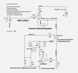
No problem, though. Here is the circuit to allow dc coupling, with 90V on the output's grid. It works equally well with 2A3, and only burns 3-5W to achieve it.
The dynamic impedance, seen by the cathode, is only a few ohms - so the output DHT keeps all its gain.
Best of all, the current is established automatically - 35mA in this case.
The second order servo filter cuts all audio out of the bias circuit at 100dB+ from 20Hz.
And, unlike the usual fixed bias circuits, there are no noisy reference diodes or zeners required.
.
however, even with 4P1L, filament bias will not be effective. The voltage and power handling are unmanageable, and we will need a ~180 ohm resistor - high enough to need bypassing, anyway.
No problem, though. Here is the circuit to allow dc coupling, with 90V on the output's grid. It works equally well with 2A3, and only burns 3-5W to achieve it.
The dynamic impedance, seen by the cathode, is only a few ohms - so the output DHT keeps all its gain.
Best of all, the current is established automatically - 35mA in this case.
The second order servo filter cuts all audio out of the bias circuit at 100dB+ from 20Hz.
And, unlike the usual fixed bias circuits, there are no noisy reference diodes or zeners required.
.
Attachments
Acording to that test they need 15Vp-p across the voice coil. So thats 172Vp-p swing on a 4P1L with a 5k primary. Thats pusing a 4P1L pretty far even though its only 3/4 watt.
It is fine if you pick a useful bias point for your application. For example, given a 5K load, if you bias the 4P1L at 230V/30 mA (Vg = -20V) with a swing of 30 V peak-to-peak you are still well within A1, have some more room in case the load changes a bit and get 195V p-p on the plate (that's 1W into the headphones!!). You only need 10.6 V RMS from the 26. I don't think there is a problem in running the 4P1L at 6.9W total plate+G2 dissipation firstly because is well within max ratings. In the end it is more efficient than other solutions primarily because it requires only less than 1.4 VA for the filament. A 2A3 needs 6.25 VA!
You might just add the 3A5 and get a true integrated amp.
Tube
71A Mu 3 Ra 1750 Vout (for 2v in) 1.2
6B4G Mu 4.2 Ra 850 Vout (for 2v in) 2.4
46 Mu 5.6 Ra 2350 Vout (for 2v in) 1.9
10Y Mu 8 Ra 5000 Vout (for 2v in) 1.8
4P1L Mu 11 Ra 2250 Vout (for 2v in) 3.7
The 4P1L gives you the most gain for a 60 ohm output impedence (my headphones), followed by 6B4G/2a3. I entered a nominal 2v input - would be higher in practice.
Last edited:
I'm sorry but it makes absolutely no sense to DC couple and filament bias via a high dissipation resistor. The whole point of filament bias is to bias the tube via a low impedance path to ground. I really see not other good way to DC couple except via a low impedance supply beneath the output tube.
I found that with a 4P1L in triode mode as the input tube there was not enough gain to drive the 4P1L output tube to its maximum output - given a standard 2V signal. I think any tube with lower gain would not do the trick.
In pentode mode the 4P1L had plenty of gain, but also a lot more odd order harmonics (and some more even order) and is less stable than in triode mode.
In pentode mode the 4P1L had plenty of gain, but also a lot more odd order harmonics (and some more even order) and is less stable than in triode mode.
I found that with a 4P1L in triode mode as the input tube there was not enough gain to drive the 4P1L output tube to its maximum output - given a standard 2V signal. I think any tube with lower gain would not do the trick.
As a stand-alone thing that's true and this is what I have been trying to say. Other output tubes, like 2A3, are even worse....
Having a 26 or 4P1L into 4P1L can work only if you don't need too much power for the headphones.
Frankly 2V input signal as a standard is a bit too high in my experience. I would rather use 0.2-0.5 V RMS as reference input signal from digital sources. Despit of this, having 0.2V input a total practical gain of the 26 + 4P1L combo (with 5K primary load for specific headphone secondary impedance) is about 39 (at the primary) which means 12 mW Pout. In some cases it is well enough in other it is not. In the latter case I would add another stage (another 26 or a 3A5 or any other similar thing) and get more gain.
Yes. The triode mode 4P1L input and output has enough gain for normal headphones. Plenty of gain - I've tested this with my 300 ohm Sennheiser and some lower impedance cans from the 8 ohm tap.
Maximum output from most DACs is either 1.5V RMS, or 2V RMS. Some portable players are lower. That's what I'm counting on, 1.5 or 2V RMS being able to just clip the amp. I can turn it down from there, if needed.
Maximum output from most DACs is either 1.5V RMS, or 2V RMS. Some portable players are lower. That's what I'm counting on, 1.5 or 2V RMS being able to just clip the amp. I can turn it down from there, if needed.
That's the beauty of 3A5 (μ=15) driving 4П1Л (μ~8) - The highest overall gain that's easy to achieve all-DHT.
It's sweetly cheap, too.
You can get more gain using my shunt cascode driver circuit - but for many applications it's enough as it is - making a simple build.
dc coupling of this pair can be achieved with the auto-bias circuit I just posted.
2A3 will work too, but the parts cost is greatly increased, and the extra gain it needs just adds complexity. Use the 2A3 if you feel you need it - but 2.5W out of a 4П1Л should suffice for the majority.
ikoflexor do you have any DHT suggestions for headphones that do not need a lot of power, ie Sennheiser HD800, 300 ohm and 102 db/1v? Some of us have no need for the huge power requirements of orthodynamic headphones.
Two stages, both with 4P1L would be just fine IMHO.
We can just run the 4P1L harder, instead of 2A3 or 300B. 9W plate dissipation for 4P1L should be fine.
Yes. Or parallel two 4P1L like Anatoliy did; he says they're not hard to match.
OK, I can try that. Oh, I'll need some 7 pin sockets.That's the beauty of 3A5 (μ=15) driving 4П1Л (μ~8) - The highest overall gain that's easy to achieve all-DHT.
 Got the 3A5s, but no sockets.
Was going to go with a 6SN7 on the input with a CSS at about 10mA - it should be nicely linear that way and enough gain.
Another advantage of 3A5:
Economy of a separate power supply for the driver stage. Both sides of a 3A5 can run 7mA at 90V, so we can have 120V to allow a CCS (with low dissipation).
Private supply for the driver usually sounds better to me - although a shunt regulator for the power-stage may reduce that benefit.
Economy of a separate power supply for the driver stage. Both sides of a 3A5 can run 7mA at 90V, so we can have 120V to allow a CCS (with low dissipation).
Private supply for the driver usually sounds better to me - although a shunt regulator for the power-stage may reduce that benefit.
- Home
- Amplifiers
- Tubes / Valves
- The all DHT SET Headphone Amp