OK, what peak voltage do we need to aim for?
And does the impedance vary over the frequency range? Is 38 ohm only a nominal?
We should be clear about the goals. If the Orthos are so different, it may not be optimum to have a single design here.
It depends very much on the actual headphone as there can be huge differences in terms of impedance vs frequency curves. Usually the nominal impedance given in specifications is true in the midrange. Then, depending on the design and technology, you can have quite some variations both in module and phase at low or high frequencies. Typical Sennheiser, for example, look very much like a tiny woofer with a peak in the module around 90-100 Hz where phase rotation in about +/- 20-25 degrees. At high frequencies there is a modest slope where impedance is higher (typical inductive behaviour). Other types instead can have a really flat (resistive) impedance from mid to low frequencies and pretty huge variation at high frequency where phase rotation can be as big as +/-45 degrees.
As a rule of thumb the Pout can range from 10 mW to 1W. Having already the phones is a clear advantage as you can taylor the amp to that specific case.
Cheers
P.S. Not necessarily the amp has to be very low Zout. Maybe this is true in most cases. There are cases where high Zout (i.e. a constant current amp) is the winner.
Will be a good idea OPT with multi tap secondaries 4-8-32-300 ohms this way we have headphone & power amp? or if can't give very good perfomance will use two OPTs: one for headphones & other for loudspeakers?
we need to decide on a tube first. The more I look at it the 4P1L just doesn't have what we need as an output tube, the curves barely allow a 100vp-p swing. Would be better off just building a spud D3A or 6C45pi SET.
I think at least a 2A3 is required to make this project worthwhile, and at that size yes it makes sense to ask for an 8 ohm tap to serve horn/small fr speakers as well.
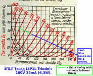
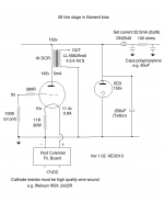
Here's my serving suggestion for the 4П1Л (4P1L) Triode, to meet Dave's 200V+ swing.
Please see the load line on the triode curves. Best load is 5300 ohm and an operating point of 180V 35mA, if the curves are reliable. I think Ale has some actual measurement, for double-checking.
With ordinary high impedance driver we should be able to swing 90V to 270V [180V] at the anode, for symmetrical grid swing.
Drive the 1st grid with a cathode follower and we will get more like 40V to 320V symmetrical and very linear - 280V swing!
for 38 ohm reflected load, the turns ratio is about 12, so you get ~23V peak to peak on the headphones with cathode follower drive or 2.5W rms, which is the expected value for the 4П1Л.
Attachments
we need to decide on a tube first. The more I look at it the 4P1L just doesn't have what we need as an output tube, the curves barely allow a 100vp-p swing.
Hi Regal,
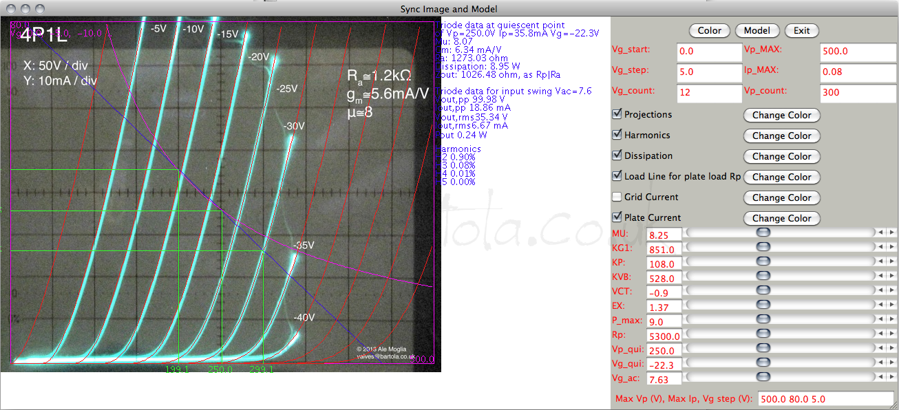
What is your basis for this conclusion? 4P1L can easily provide 100vpp swing and more, you can swing the anode up to 100vrms in class A1. Here is a real example for a 5K3 load as suggested by Rod. The operating point is really good anywhere between 230-250V:
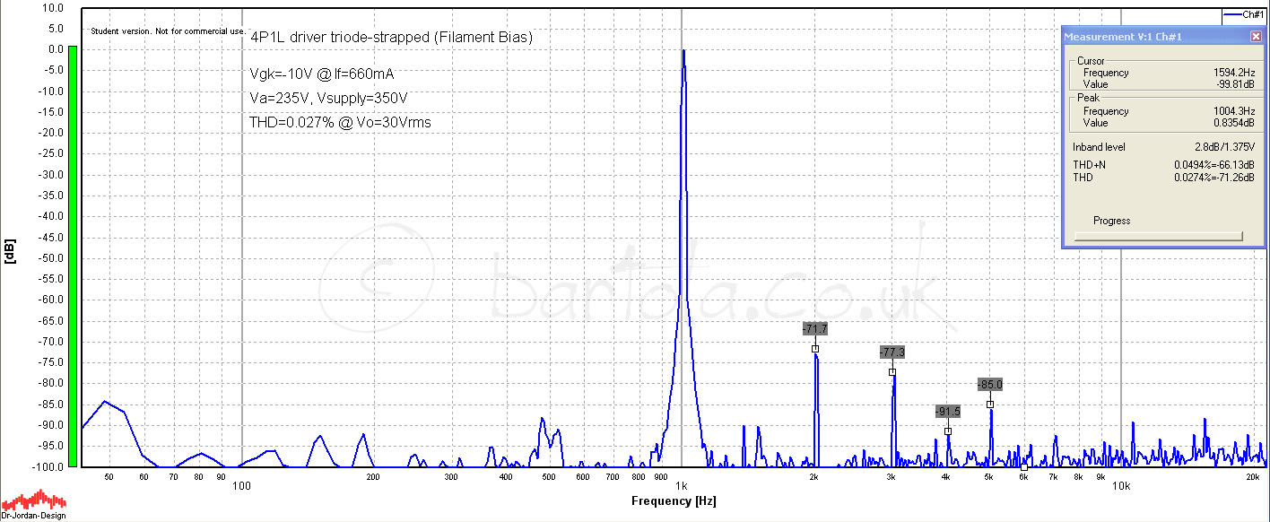
Also, 4P1L is extremely linear valve. Here is the valve's intrinsic distortion at 30Vrms:
Very interesting thread indeed. I like Rod's approach. I started experimenting with the 6e5p in cathode follower with a autobias circuit to avoid caps in the signal path. I never progressed with the idea. Here is the old thread: http://www.diyaudio.com/forums/tubes-valves/212978-6e5p-wcf-headphone-amp-no-cap.html
Cheers,
Ale
Last edited:
Hi Regal,
What is your basis for this conclusion? 4P1L can easily provide 100vpp swing and more, you can swing the anode up to 100vrms in class A1. Here is a real example for a 5K3 load as suggested by Rod. The operating point is really good anywhere between 230-250V:
Ale
Just being devils advocate before I invest in the iron. The load lines are obvious to me that the 2A3 is more linear swinging 200Vpp than the 4P1l.
But it could very well be acadimic. Just want to make sure we get a solid upgrade over a 6c45p1/C3g/D3A type spud SET (they are tough to beat with practically no caps in the signal path, very pure.)
Have you tried driving a 4P1L with another 4P1l into class A1 with a gyrator mu-follower/cap load? Honestly would prefer keeping this 2 tubes max (i.e. no cathode follower.)
Thanks Rod, do you think a two stage 4p1L with the driver gyrator mu follower loded/cap cpoupled would have enough to drive the grid poitive for close to the 280V swing?
Driving the grid positive to +8 or 12V is needed for full power, and we should allow for 10-15mA of 1st-grid current to do it properly. This means dc-coupling, in effect, since this high quality design will not suffer to have a large-value cap.
I think that some kind of auto-biassing can be realised to make this simple - I will draw it up when I get a minute.
According to my experiments, 4П1Л in A1 triode mode with 250V B+ and 5K load is capable to produce 1.8 W of pristine clean output power. When driven in A2 up to +12V on G1 it is capable of 2.5 W of pristine clean power. I described the result of experiments in this topic: http://www.diyaudio.com/forums/tubes-valves/183329-one-more-4p1l-se.html
The final schematic can be used for headphone amps as well, with appropriate output transformer.
The final schematic can be used for headphone amps as well, with appropriate output transformer.
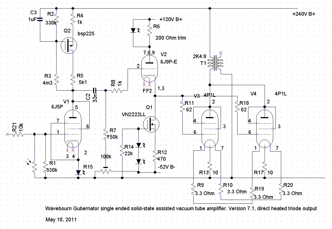
Well, I've built quite a few line stages with DHTs by now. All different kinds - 10Y, 46, 01A, 3a5, 71A, 12A, long list. My preference swings between the 4P1L and 26 depending on the implementation. I'm a very big fan of Anatoliy's work - he's a pioneer - and I haven't built and heard his circuit. But I can't agree with "zero advantage of DHTs". My current favourite input stage has swung back to the 26, as shown in the schematic. If I was to build right now, I'd use this stage into a 4P1L stage in filament bias. It really has a bit of magic about it for me - the 26 can do that.
Attachments
I mean zero advantage when maximal swing of anode voltage required is about 20 volts, and the tube will never go into cut-off region because output tube will saturate way before that happens.")
Correct that is what I am saying about the fact that we want this DHT headphone am to have an advantage over what I call the "spud" SET headamp.
I conside the spud the "competition" as it remains an excellent performer, several of us on this forum built variations on the them when the SSHV came out.
Bassically just a common cathode stage with a super tube (WE417, 6c45pi, d3a,or cg3, etc). Uses LED bias and an SSHV and there literally are no caps in the signal path, about the purist SET sound you can get, but they tend to start to have too much distortion around half a watt.
Now we are "back" to DC coupling make sense with our the DHT SET, Wavebourn hass done an excellent job explaining why the preferred method here is to DC couple.
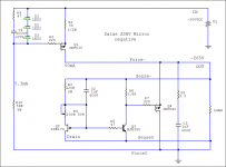
I found a "negative" version of the SSHV that could make this easier (attached). Also looks like a gyrator mu output loaded 4p1l can drive a 4p1l into A1. One could install a switch to where high efficient phones get the plate output and the inefficient phones get the mu output. (sort of like the p-p guys with their triode/ultra-linear switch.)
What are the thoughts of using two 8 ohm windings on the opt transformer's winding to give 5k:32 ratio balanced ouput? Its a way to get away from the high DCR/inductance of a headphone secondary.
Could have several outputs: high efficient phones/speakers get the two 8 ohm secandaries in parallel, while the low efficiency jack could be a "balanced" 32 ohm output.
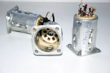
Also check out the loctal sockets I found on ebay. Can the 4P1L re run upside down?
Attachments
Last edited:
Also check out the loctal sockets I found on ebay. Can the 4P1L re run upside down?
It seems can run upside down, inside locatal sockets are the same that I have on hand.
Also check out the loctal sockets I found on ebay. Can the 4P1L re run upside down?
Rather uncommon to run a tube upside down
I understand horizontally mounted, but pointing down? What about the heat issue?And those are ugly loctal sockets... hiding most of the tube although I doubt that the 4P1L will fit inside. When you need good loctal sockets... Germany has a good supply of them new. Can send you some...
If I was to build right now, I'd use this stage into a 4P1L stage in filament bias. It really has a bit of magic about it for me - the 26 can do that.
I think it is a good idea for low power SE amp because the 4P1L is quite efficient and does not need a big swing like the 45 (which is better used in PP for me!
)Have you tried the 4P1L at full power, something like 250V/32 mA into 5K OPT and the 26+IT?
Last edited:
Regal says...
"Correct that is what I am saying about the fact that we want this DHT headphone am to have an advantage over what I call the "spud" SET headamp.
I conside the spud the "competition" as it remains an excellent performer, several of us on this forum built variations on the them when the SSHV came out.
Bassically just a common cathode stage with a super tube (WE417, 6c45pi, d3a,or cg3, etc). Uses LED bias and an SSHV and there literally are no caps in the signal path, about the purist SET sound you can get, but they tend to start to have too much distortion around half a watt."
Regal,
Are there any discussions of this here @ DIY that you could pont me too ?
thanks in advance,
dennis h
Yes - see the other thread. Today I will try to determine what the optimal load is for the 4P1L triode strapped SE. 8K? 5K? 3K?Have you tried the 4P1L at full power, something like 250V/32 mA into 5K OPT ...
I make it at about 5300 ohms -
please see:
http://www.diyaudio.com/forums/tubes-valves/228625-all-dht-set-headphone-amp-4.html#post3352853
please see:
http://www.diyaudio.com/forums/tubes-valves/228625-all-dht-set-headphone-amp-4.html#post3352853
Regal says...
"Correct that is what I am saying about the fact that we want this DHT headphone am to have an advantage over what I call the "spud" SET headamp.
I conside the spud the "competition" as it remains an excellent performer, several of us on this forum built variations on the them when the SSHV came out.
Bassically just a common cathode stage with a super tube (WE417, 6c45pi, d3a,or cg3, etc). Uses LED bias and an SSHV and there literally are no caps in the signal path, about the purist SET sound you can get, but they tend to start to have too much distortion around half a watt."
Regal,
Are there any discussions of this here @ DIY that you could pont me too ?
thanks in advance,
dennis h
http://www.diyaudio.com/forums/headphone-systems/134603-single-ended-headphone-amplifier-2.html
http://www.diyaudio.com/forums/headphone-systems/209398-spud-amps.html
http://www.diyaudio.com/forums/tubes-valves/173233-help-me-decide-headphone-amp-parafeed-normal-tx-7.html
Most moved to LED bias the cathode, a lot of us have sort of secretly built these high gm shunt regulated spud headamps. You learn the hurdles of creating that black background required for sensitive phones like grado and beyer. These readings are a good pre-requisit for this DHT project. Note I don't think there was ever a consensus between para-feed vs single feed. Adamus had one of the nicer builds.
They generally run out of steam with much more than 1/4 to 1/2 a watt. But sound absolutely top notch with high end Grados, Beyers, and Senns.
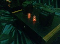
Attached is mine ( I wonder if E-print would rewind my 5k:32 OPT's with a bigger gap for a DHT output?)
Attachments
- Home
- Amplifiers
- Tubes / Valves
- The all DHT SET Headphone Amp