Yes but I think headphones sound good transformer coupled. Its not at all uncommon to spend near $1k on headphoes so why not get a good OPT to go with it?
That parafeed sowter with mu metal hybrid core looks very tempting. Its 2W at 50 hz and .5 w at 20 hz.
Running a 4P1L at 70V's is not "Fun" its a big compromise, not what this thread is about honestly.
That parafeed sowter with mu metal hybrid core looks very tempting. Its 2W at 50 hz and .5 w at 20 hz.
Running a 4P1L at 70V's is not "Fun" its a big compromise, not what this thread is about honestly.
Last edited:
Transformer coupled DHT is a high-quality solution to the problem, there is no doubt.
I am trying to emphasise the point that it works ONLY if the component and power supply quality is high. Driving $K headphones with a cheap transformer, or skimped power - makes no sense at all.
For any DIYers without the cash to acquire transformers at the Sowter level, the solution is not to use a cheap alternative transformer - the solution is to use FET-assisted triodes, or some variation on it, IMO. The capability of this kind of architecture will surprise some DIYers, I am sure.
Are these the design goals?
-Must provide 100-500mW power for low and high efficiency 600 ohm impedance range headphones
-Must provide 1.5 watts of power for low efficiency 32 ohm range headphones
-Must provide xx power for xxxx headphones acquired at a later time based on whim
-Must be transformer coupled DHT tube
The Sowter headphone transformer line seems to be the only pre-designed transformers to fit this bill if all signal line transformers are to be completely disregarded because of the DCR assumption.
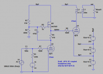
I don't follow your argument here - the filament supply is floating, so it's only earthed through the 4.3K resistor, as is the signal. Am I missing something?
The signal is in the filament bias resistor loop, it doesn't dip to the 4.3K resistor which is just elevating the ground, just like biasing a DC heater with an indirect heater tube.
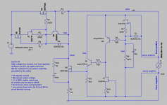
So the big cap is not in the signal path, just there as noise filter. This design is filament bias (no cathode bypass cap) with an elevated filament. It is means to have DC coupling without a cathode bypass cap. The #26 was chosen over the 4p1L for the first stage in order to keep the B+ lower so that the SSHV2 can be used.
Just want to clarify that what I posted earlier is NOT Rod's design. As far as I know his schematics are not in the open domain. My circuit uses a cap multiplier, not a gyrator, and a CCS. Just sayin'!")
Yes I know they are different but you reported silent background with a #26 preamp so that it good enough I think. I believe Rod's designs have been posted, the secret sauce is the high performance transistors ( I have a couple of his kits that I've been itching to try on an all DHT SET.)
I am open to the hybrid solution, but not at a 70V plate no way.
The question is what is a good quality output transformer? Of those mentioned is Sowter the only way to go ?
The supply voltage in my design was carefully considered. Just like you, my first thought was that it won't work so low. But 70V is fine for a 4P1L cathode follower. Please look at the curves - the anode current is almost constant in this design (thanks to the FET), so you can get away with only 3.5-4V of bias, without problems. The 4P1L only operates in a tiny curve around the operating point, so high voltage is not needed at all.
This is completely different from the usual common-cathode circuit, where higher voltage will be needed.
Other trafo makers can match Sowter quality, but none of them are willing to make the customised trafo we need. Sowter's catalogue is full of curious designs - some of which no doubt stem from this kind of project.
.
Attachments
Last edited:
The #26 was chosen over the 4p1L for the first stage in order to keep the B+ lower so that the SSHV2 can be used.
I would be surprised if SSHV2 cannot do 260V.
On the topic of transformers. For 32 ohm headphones, is the Edcor 25W, 1250 to 8 ohm not good enough?
http://www.edcorusa.com/p/465/cxse25-8-1_25k
For 50 or 64 ohm headphones, how about the Edcor 25W, 1250 to 16 ohm?
http://www.edcorusa.com/p/467/cxse25-16-1_25k
And if you can't find a HV shunt reg that can do 260V output here's what I use. It'll be very quiet and outstanding output impedance. You do need to know what you're doing to get a good pcb. More info about it you can find in this following old thread http://www.diyaudio.com/forums/power-supplies/197332-hv-shunt-regulator.html
Attachments
No the SSHV2 is good to 450V, when you DC couple it just makes since to use a tube for the first stage that operates linearly at a lower plate voltage, when you DC couple B+ is the addition of the first tube's plate, the second tubes plate, and the second tube's cathode. So 260V isn't the issue, over 450V is the issue.
I guess I wouldn't give up on DC coupling, especially since I showed how to filament bias the output tube. This gives the minimum caps in the signal path (first and second tube filament biased and no coupling cap.)
I guess I wouldn't give up on DC coupling, especially since I showed how to filament bias the output tube. This gives the minimum caps in the signal path (first and second tube filament biased and no coupling cap.)
The signal is in the filament bias resistor loop, it doesn't dip to the 4.3K resistor which is just elevating the ground, just like biasing a DC heater with an indirect heater tube.
So the big cap is not in the signal path, just there as noise filter. This design is filament bias (no cathode bypass cap) with an elevated filament. It is means to have DC coupling without a cathode bypass cap.
No - I still don't get it. Think of the filament+filament resistor 32 ohms as simply the filament supply. The signal goes to ground through the 4.3K resistor. It can't go to ground through the filament supply because that's floating. So the cathode bypass does have the same effect as it usually does. I can't see there's any free lunch here.
OK then leave off the cap that is parallel to the 4.3k resistor, the tube is biased, there is little to no degeneration since the "battery" bias exponentially greater than the tube's bias. I just put the cap there for noise reduction, I think it could be .1uf. See what I am getting at? The signal can't can't go below the "battery".
I guess I don't see the need, the input tube will would not be powered by the SSHV because it would have a CCS or gyrator. If we use a negative supply for the input tube to enable a dc couple then we need to add a coupling cap at the input, so no benefit.
I think what I posted a few pages back makes the most sense and has no practically no caps in the signal path. I'll add detail to it and attach the asc file this weekend.
I think what I posted a few pages back makes the most sense and has no practically no caps in the signal path. I'll add detail to it and attach the asc file this weekend.
OK then leave off the cap that is parallel to the 4.3k resistor, the tube is biased, there is little to no degeneration since the "battery" bias exponentially greater than the tube's bias. I just put the cap there for noise reduction, I think it could be .1uf. See what I am getting at? The signal can't can't go below the "battery".
I still don't get it - the filament supply + 32 ohm resistor constitutes just a kind of "augmented" filament supply. It has no effect on the the signal circuit until it's grounded, which it is through the 4.3k resistor. The 32 ohm resistor is fairly insignificant in proportion to the 4.3K resistor. So effectively this looks to me no different from a floating filament supply grounded through a 4.3K resistor, which would then usually be cathode bypassed.
Can anyone else cast some light on this?
You can't get rid of the cap across the 4k3 resistor if you want the tube to properly amplify the signal. If you want to get rid of that cap you need a stacked supply. Then the 4k3 resistor also disappears. Which also makes the filament bias useless. So, if you want DC coupling then you either to the resistor plus cap, and the filament bias is useless IMHO, or you have a stacked supply, and the filament bias again brings nothing to the table.
Myself, not sure how much of a fan of DC coupling I am... is the effort and complications worth it?
Myself, not sure how much of a fan of DC coupling I am... is the effort and complications worth it?
Attachments
If we use a negative supply for the input tube to enable a dc couple then we need to add a coupling cap at the input, so no benefit.
I wouldn't be so sure about this statement. In real world things tend to be not so simplistic. Firstly the input cap can be as good as it gets, secondly it would be a small size cap and last, but not least, it works at rather modest signal level.
45
Last edited:
- Home
- Amplifiers
- Tubes / Valves
- The all DHT SET Headphone Amp