Ooops! 1VRMS in gives 19mW out into 32 Ohms @ 1kHz - that missing bit of information might help.
How can you get 19 mW into 32R with just 20mA idle current and RC coupling? For that power you need over 24 mA r.m.s or 34.5 mA peak which the 6A4 running at 20 mA clearly can't do. If distortion has be low at 0.04% then you need a LOT more than this. Into 32R if you get some 3-4 mW with acceptable distortion is already some result. Probably it works with the 32R Audio-Techinca AD700 because this is a sensitive headphone that only needs 0.9 mW for 100 dB SPL.
Also 19 mW into 32R means less than 0.8V r.m.s. output. Has your input transformer got a big step down?
I think your amp might work with 600R at that power level but still I am not sure about 0.04% THD.
The Zout of the 6A4 common cathode is in the Kohms range I think. You might need a 6C33 running at about 500mA to get about 100R Zout in your circuit. The Zout is not the parallel impedance with 32R.
Hi Merlin,
Good question. I have reviewed my measurement spreadsheet and it shows output impedance of -105 Ohms at 1kHz. I did not notice the negative sign when I first posted my results!! ooops
Let me recap the measurement method I used.
All the calculated output impedances are negative and are between -95 Ohms and -105 Ohms. I think I have made a mistake somewhere (my apologies for not noticing before I posted) - have you any suggestions to correct the calculation?
Bondini
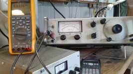
PS: In addition to the HP bench-top supply, the the test set up included an HP4204 sine wave generator as the input, with the output measured on an HP331A distortion analyser/true RMS voltmeter. All the HP equipment has been check and confirmed against calibrated instruments. On the day, I checked and confirmed output voltages on a calibrated Fluke 289.
Good question. I have reviewed my measurement spreadsheet and it shows output impedance of -105 Ohms at 1kHz. I did not notice the negative sign when I first posted my results!! ooops
Let me recap the measurement method I used.
- I set the input to the amp at 1 V RMS.
- I measured Vout RMS into a 32 Ohm resistor from 20 Hz to 40 kHz, entering each result into my spreadsheet.
- I repeated the procedure for a 56 Ohm resistor.
- I set the spreadsheet to calculate Zout = (Vout56 - Vout32)/((Vout 32/32)-(Vout56/56)).
All the calculated output impedances are negative and are between -95 Ohms and -105 Ohms. I think I have made a mistake somewhere (my apologies for not noticing before I posted) - have you any suggestions to correct the calculation?
Bondini
PS: In addition to the HP bench-top supply, the the test set up included an HP4204 sine wave generator as the input, with the output measured on an HP331A distortion analyser/true RMS voltmeter. All the HP equipment has been check and confirmed against calibrated instruments. On the day, I checked and confirmed output voltages on a calibrated Fluke 289.
Hi 45,
The input transformer is 1:1, no step-down or step-up.
For 1 Vrms input @ 1kHz, the measured Vout across the (measured) 32.76 Ohms was 0.785 Vrms, and 1.94 Vrms across the (measured) 55.5 Ohm resistor.
THD was 0.04% @ 1kHz and stayed under 0.1% from 320 Hz to 24 kHz. The HP331A was checked against a calibrated AP1 in November 2018 and was shown to be accurate and reliable.
Bondiniu
The gain <1 might be due to the vertical load-line.
Still I don't believe you can get 19 mW into 32R with LC coupling and just 20 mA anode current. You need a step down transformer. 19 mW into 32R requires 34.5 mA peak which you cannot get out of 20 mA quiescent current. It will clip heavily on one side of the sinusoid at least. I don't believe distortion numbers as well.
The 6A4 is close to the type 33 in terms of anode curves. The 6A4 in triode mode has gm 2.1-2.2 mA/V, mu about 6 and plate resistance about 2.8 Kohm at 150-160V plate voltage and 20 mA anode current; Type 33 (you can see in the data-sheet below in the link) in triode mode has mu =5.2, gm=1.75 ma/V and plate resistance 3 Kohm.
Please draw a 32R loadline for 158V/20mA (so that at -15V bias can give you full swing without going into positive grid) and see if you can get 19 mW. Then calculate what large 2nd harmonic distortion you get even without taking into account higher orders. The triode curves are on the last page. https://frank.pocnet.net/sheets/049/3/33.pdf
N.B.
Two of the gird voltage numbers are wrong. It's clearly in steps of -5V so instead of 0,-5,-10,-20,-30, -25,-30 (again?)....it reads 0,-5,-10,-15,-20, -25 , -30 etc...
Hi 45,
The loads on the type 30 and the load on the 6A4/LA are the chokes. There static load is their winding resistance of approx 400 Ohms (measured).
However, the loadline they present to signals is nearly horizontal as their reactive impedance rises with frequency, as they act almost as constant current sources.
The plate curves for both the type 30 and the 6A4/LA triode are very linear indeed. With the sort of horizontal loadline that a choke provides, I would expect very low distortion from both devices.
Bondini
Are you sure you are measuring volts r.m.s.?
If 0.785V were peak-to-peak then I could believe it because it would mean 2.4 mW. For this the 6A4 would need to swing about 12 mA peak which quite possible.
Still I don't believe it would do that with distortion as low as 0.04%.
The horizontal loadline is not what you get when you connect the headphones. If the headphones are connected the load is 32R which is a very vertical loadline no matter how big is the anode choke and the dummy output resistor. This also means that 10 uF into 32R result in 500Hz at -3 dB.
Hi 45,
19mW @ 20mA requires a signal swing of a bit under 1V rms at the valve anode/choke node. The choke holds the anode current pretty constant at 1kHz, as well as permitting the anode signal voltage to swing above and below the supply voltage. Achieving that output power was indeed possible.
Bondini
19mW @ 20mA requires a signal swing of a bit under 1V rms at the valve anode/choke node. The choke holds the anode current pretty constant at 1kHz, as well as permitting the anode signal voltage to swing above and below the supply voltage. Achieving that output power was indeed possible.
Bondini
The choke is not the load. Actually it is there to unload the tube as much as possible! So I have to assume that you are not using any 32R load to measure the power. That's the mistake then. You are never going to get 19mW into 32R with that circuit.
Put a simple 32R resistor in parallel with the 470K dummy resistor and see what you get. That's the power you will get into the headphones and will also see that THD is much worse than 0.04%. Then also measure the output at 500Hz and you will see that when the 32R load is in place your output voltage is 3 dB down. Little to no bass with just 10 uF...you will need 20-25 times more capacitance to get full bass.
Put a simple 32R resistor in parallel with the 470K dummy resistor and see what you get. That's the power you will get into the headphones and will also see that THD is much worse than 0.04%. Then also measure the output at 500Hz and you will see that when the 32R load is in place your output voltage is 3 dB down. Little to no bass with just 10 uF...you will need 20-25 times more capacitance to get full bass.
Last edited:
Hi 45,
No need for magic or for apologies.
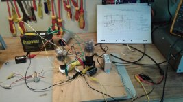
I encourage you or any other interested reader to experiment and discover my mistakes. To help, I have posted my schematic diagram, a picture of my rats nest test rig, details of the equipment that I used, and the basic results of the tests.
Bondini
No need for magic or for apologies.
I encourage you or any other interested reader to experiment and discover my mistakes. To help, I have posted my schematic diagram, a picture of my rats nest test rig, details of the equipment that I used, and the basic results of the tests.
Bondini
Bondini, it's about Ohm's law . If your quiescent current is 20 mA then in THEORY this is the max undistorted PEAK current it can deliver. If the load is 32R it means 6.4 mW. However because devices are not perfect it will be affected by quite a lot of distortion. Easily around 10%...if not more!
Always in theory if you want 19 mW you should run the tube at least at 34.5 mA. But this again will be affected by high distortion. So you will need a lot more quiescent current or much simpler and better a decent and suitable output transformer! A proper gapped output transformer will also remove the nasty low frequency resonance.
Always in theory if you want 19 mW you should run the tube at least at 34.5 mA. But this again will be affected by high distortion. So you will need a lot more quiescent current or much simpler and better a decent and suitable output transformer! A proper gapped output transformer will also remove the nasty low frequency resonance.
Hi 45,
An excellent point, prompting me to re-assemble and re-test the rats nest circuit that gave the original results. This time around:
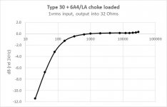
The results this time were that 1 Vrms in gave 12.3 mW into 32 Ohms with .043% THD. The frequency response was better behaved this time and is down 3 dB at 80 Hz.
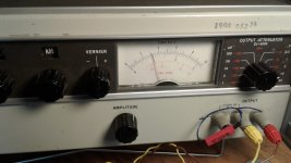
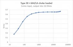
I have attached images of the HP4202 input oscillator, the re-built rats nest, and the Hp331A with the Fluke 289 sitting on top showing the RMS output voltage. I have also attached plots of the frequency response (dB relative to 1 kHz, and Vout rms versus frequency) along with a plot of THD versus output at 1 kHz.
If your quiescent current is 20 mA then in THEORY this is the max undistorted PEAK current it can deliver.
An excellent point, prompting me to re-assemble and re-test the rats nest circuit that gave the original results. This time around:
- the layout was tidier;
- the heater supply, B+, chokes and caps were the same; but
- the resistors and the valves were whichever came out of the box to match the schematic.
The results this time were that 1 Vrms in gave 12.3 mW into 32 Ohms with .043% THD. The frequency response was better behaved this time and is down 3 dB at 80 Hz.
I have attached images of the HP4202 input oscillator, the re-built rats nest, and the Hp331A with the Fluke 289 sitting on top showing the RMS output voltage. I have also attached plots of the frequency response (dB relative to 1 kHz, and Vout rms versus frequency) along with a plot of THD versus output at 1 kHz.
Attachments
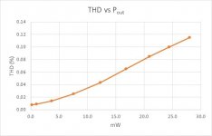
Wow almost 30 mW with 0.12% THD! Why don't you show the load in schematics and the test points for the signal measurement?
As it is your circuit cannot manage more than few mW's with acceptable distortion into 32R, IMHO. Certainly not 0.04% or so...... This numbers are really questionable and it is really unclear what you measure and how you figure them out even assuming that all your tools are ok.
You are the only on Earth with such a claim. Or at least I have never heard or manage to get this. How people missed this in almost 100 years? I think I have nothing more to add. If you really think everything is alright then bring it to some independent party that can double check with his own tools and you might get something like a Nobel price if you are right. Sorry but I don't believe it.
Hi 45,
Thank you for your comments, suggestions and questions. To answer your most recent questions, the 32 Ohm load is across the output - that is, in parallel with the 470 kOhm output resistor on the schematic that couples the output capacitor to the signal ground. The measurements are taken across the 32 Ohm resistor.
Of my tools, I most trust the HP4024A oscillator and the Fluke 289 - the HP has been refurbished and Fluke is factory calibrated. I am confident that both are correct.
The RMS voltmeter of the HP331A gives readings very close to those of the Fluke. The distortion measurements have been good in the past, and I assume they are still good, though I have no instrument with which to correlate or check them. I cannot say for certain that they are correct.
I don't think my circuit is very original - for instance, referring to english-language sources, Terman includes a section on what he calls "impedance coupling" using choke loaded valves at pages 371 and 374 of his Radio Engineers' Handbook, McGraw-Hill, London, 1950, and the the Radiotron Designer's Handbook (1956) discusses choke coupled amplifiers at pages 559 and 560.
More recently, Alan Kimmel and John Atwood combined talents to design and build (respectively) a choke assisted mu-stage as a driver for a single-ended parafeed amplifier (pages 4 to 7 of Vacuum Tube Valley, Issue 20, 2003), and Patrick Turner (2017) offers another approach here: audiofilterchokes-page3
So I doubt that I am the first to make this sort of amplifier produce this sort of output into a 32 Ohm load. I am sure designers and constructors in other countries have made similar experiments with maybe even better results. Perhaps they also deserve Nobel prizes?
Bondini
Yes you are the first because you are basically denying the Ohm's law.
Please explain HOW you can get an output current into the 32R load larger than the quiescent current with little distortion in a SE class A stage. The impedance coupling in your circuit is quite bad because the 6A4 was never designed to work straight into 32R. The choke has the only function to make the circuit as efficient as possible but certainly is a passive device. I don't think the Radiotron or other books talk about this. I can check but I really doubt it.
Please explain HOW you can get an output current into the 32R load larger than the quiescent current with little distortion in a SE class A stage. The impedance coupling in your circuit is quite bad because the 6A4 was never designed to work straight into 32R. The choke has the only function to make the circuit as efficient as possible but certainly is a passive device. I don't think the Radiotron or other books talk about this. I can check but I really doubt it.
Last edited:
Actually at p. 559 of the Radiotron as you suggest there is a very nice formula which tells you the maximum efficiency of a triode. This is:
eta = RL[2RL + 4ra]
in you case ra is about 3K and RL=32R which results in maximum efficiency of a "whopping" 0.26% !!
The anode dissipation is about 3W which means the the max Pout at clipping, and thus with quite some distortion in the 5-10% range, is not even 8 mW.
As I said before the max peak current in the IDEAL case would be 14.14 mA R.M.S. and this means 6.4 mW. However because the device is not ideal there will enough 2nd harmonic distortion (5% or more) that will cause some increase in average current will be a bit higher. Here is where those 8 mW are coming from.
Forget 19 mW at 0.04% or 30 mW at 0.12%. They do not make any sense.
- Home
- Amplifiers
- Tubes / Valves
- The all DHT SET Headphone Amp