You got 2) wrong.
Now is OK?
Attachments
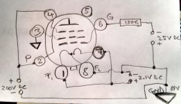
Sure, but I insist that when you get help, you make an effort and do things as detailed as possible. Your picture did not include the resistor, or the power supplies properly labeled. You make it difficult for us to give you help. When someone helping you puts more effort into making a picture that only helps you, you should be worried! ")
You start with 100V, to be safe. Then increase slowly while monitoring the current, until you get to 200V, which is the target that you want the tube tested at. If you got to 200V on the plate, while you have -25V on the grid, and you measure, maybe 10mA current through the tube, you can then start adjusting the voltage on the grid, slowly, watching the current going up. When you get to the desired current, which maybe it is 20mA or so, then you write down what voltage you have on the grid. Could be -14V or could be -16V.
But if you don't have a variable high voltage supply perhaps you can start directly with +200V on the plate, and only adjust the grid voltage from -25 towards -15 while monitoring the current.
But if you don't have a variable high voltage supply perhaps you can start directly with +200V on the plate, and only adjust the grid voltage from -25 towards -15 while monitoring the current.
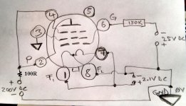
To monitor the current I do like the #26 tube: putting 100R between B+ & tube plate?
Yes, and you measure the voltage across that 100R resistor. The current will be the measured voltage divided by 100.
First of all sorry for my bad English, I will try again:
I have measured the voltage across the resistance of 100 ohms with the voltages of the schematic and it measures 0V, I lowered gradually from -25V up to -0V monitoring the current and up to -6,65V the voltage across the resistance measures 0V, the maximum voltage across the resistance is 0,583V when there is applied -0V on the grid.
I have measured the voltage across the resistance of 100 ohms with the voltages of the schematic and it measures 0V, I lowered gradually from -25V up to -0V monitoring the current and up to -6,65V the voltage across the resistance measures 0V, the maximum voltage across the resistance is 0,583V when there is applied -0V on the grid.
- Home
- Amplifiers
- Tubes / Valves
- The all DHT SET Headphone Amp