I'm using a lab bench supply for the filaments. Will look into high voltage regulation.Are you using coleman rges for the fiament ? Getting rid of the hum an you will be amazed at the overall sq improvement.
At the moment I'm using Cinemag 1:1 for the DAC output. There seems to be plenty of level as I run most tracks at -4dB to -6dB. Bass is a little loose, so maybe the DCR of the output transformers is too high. Will see what I can find.
As good as it sounds, it does seem like a huge complication for just a little voltage and current gain. There must be an easier way, but is there an easier way that sounds good?
I'm using a lab bench supply for the filaments. Will look into high voltage regulation.
Have you tried dialing down the grid leak resistor? Maybe it will pick up less radiated hum.
Thanks for answer, what about the pòwer in mA?
I would specify it for the actual DC current + 10-15%. If you need 30 mA then ask for 35 mA. This way you can get higher inductance for a given size without increasing insertion loss which you will have with higher DC current requirement (i.e. using a smaller gap which translates in higher permeability rather than increasing the number of turns with bigger gap).
Less turns = less leakage inductance. So if the geometry is well choosen you also get better high frequency behaviour.
Regarding the PX4 and 307A, I agree.
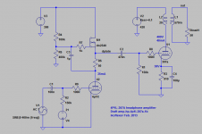
Still, some people do have some 307a, so here's the draft I have, in which the 307a is biased a bit on the hot side. The thd simulation is a case scenario that's interesting to me. A relatively realistic volume level for my headphones.
Compare that with having gm-70 in the output stage. :/
The question is, would anyone ever hear the difference?
Sorry my ignorance Iko, could you let me know:
-How much current for: V2, V3, V4 & V5?
-Heaters 307A: 5.5V 1A?
-Wich is the grid of 307A, G2?
Last edited:
You'll be extremely lucky if they have any in stock, let alone at that price. They've been off the radar for a while now.
I have two pairs (one here and one in Italy). If someone wants them just send me a pm. I will give them away for a reasonable price (i.e. the same price I paid) as I don't think I will ever use these....
I've changed the bias for both tubes. The 4P1L with 240V at about 35mA, and the 307A 360V across at about 38mA. There's been some discussions in other parts of the forum where people talked about the best operating point for the 307a.
Depending on the particular tube you have, the 4P1L may need around -21V on the grid.
For the 4P1L I show fixed bias just to keep the drawing simple, but I would use filament bias with a 32R resistor (650mA filament current). In my opinion it's impractical to do filament bias with the 307a. You'd a 38R resistor that would continuously dissipate 38W, for one tube. So, for the 307a you can choose fixed bias or self-bias as shown in the schematic.
Don't take the values in the schematic as absolutes. In the real world you may have to change some values to get the bias to what you want, especially around the DN2540.
Attachments
I have two pairs (one here and one in Italy). If someone wants them just send me a pm. I will give them away for a reasonable price (i.e. the same price I paid) as I don't think I will ever use these....
YHPM
Aaaand, I'd like to remind everyone that this little project linked below is absolutely excellent if you want extremely low distortion, and in general pristine numbers.
Audio Buffer in english
Audio Buffer in english

Using a shunt regulator at such high voltage and current is quite a tour de force. I've designed and built a few. A lot of care goes into what devices to use and how they dissipate the heat, at steady state as well as ramping up to steady state. It's not for the faint of heart. Just saying.
- Home
- Amplifiers
- Tubes / Valves
- The all DHT SET Headphone Amp