Well a few days ago I finally got all the parts for my amp together and started soldering it together. At first it didn't work, but that's because I blew the fuse without realising it. Anyway, I started playing around with it and I was getting the correct voltages out of the transformer and the heaters worked fine. Then I plugged in the rectifier tube, a 5y3gt, and ran into some trouble.
I'd like to say first that I don't know what the rectifier should have done, this having been my first tube project. I plugged in the rectifier with the other tube sockets empty and the rectifier started glowing orange at the base, then the flat part on top turned blue and one of the big verticle things (the plates?) started glowing bright orange. The other one didn't glow at all, so I figured something was wrong, but I didn't know which side.
I played around with the wires for a while, making sure everything was correct and it was. Well the bright orange piece made me think it was getting too much voltage, so I reversed the wires going from the transformer to the tube plate--filament thinking they may have been done backwards with the 275v secondary going to the filament. After a second or two of running that way, the tube didn't do anything, but the transformer smelled like burning and the 5v secondary wires started melting their insulation.
Now the transformer just buzzes and gets really, really hot if i turn it on attached to anything or not, so I'm assuming it's gone.
So what should the rectifier have done when I turned it on? Should it have been glowing orange and blue like it was?
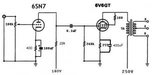
Also, this is the schematic I used. I was told that the 6sn7 is running at too low a voltage (it would have been about 220v, not 180v), so I suppose I can increase that now that I need to buy a new transformer. What voltage should I use?
Thanks a lot,
Andy
I'd like to say first that I don't know what the rectifier should have done, this having been my first tube project. I plugged in the rectifier with the other tube sockets empty and the rectifier started glowing orange at the base, then the flat part on top turned blue and one of the big verticle things (the plates?) started glowing bright orange. The other one didn't glow at all, so I figured something was wrong, but I didn't know which side.
I played around with the wires for a while, making sure everything was correct and it was. Well the bright orange piece made me think it was getting too much voltage, so I reversed the wires going from the transformer to the tube plate--filament thinking they may have been done backwards with the 275v secondary going to the filament. After a second or two of running that way, the tube didn't do anything, but the transformer smelled like burning and the 5v secondary wires started melting their insulation.
Now the transformer just buzzes and gets really, really hot if i turn it on attached to anything or not, so I'm assuming it's gone.
So what should the rectifier have done when I turned it on? Should it have been glowing orange and blue like it was?
Also, this is the schematic I used. I was told that the 6sn7 is running at too low a voltage (it would have been about 220v, not 180v), so I suppose I can increase that now that I need to buy a new transformer. What voltage should I use?
Thanks a lot,
Andy
Attachments
Sounds like your supply is running into a dead short. Check your wiring and especially the polarity of the supply electrolytics.
What I like to do is estimate the current that a circuit will draw, calculate the equivalent resistance load (Ohm's Law) and power, substitute an appropriate resistor across the supply output, then test the power supply on its own. Then before connecting the supply, use an ohmmeter to make sure that the actual load isn't shorted or unusually low resistance.
What I like to do is estimate the current that a circuit will draw, calculate the equivalent resistance load (Ohm's Law) and power, substitute an appropriate resistor across the supply output, then test the power supply on its own. Then before connecting the supply, use an ohmmeter to make sure that the actual load isn't shorted or unusually low resistance.
Psu burnouts
I learnt the hard way, don't feel ashamed. I did a silly thing back in the 1950's when I wired valve bases incorrectly seeing them from the wrong way.. Notice decent quality bases also have numbers next to the tags.
You obviously had a serious short in the HT side to make the rect go blue / orange. The transformer is a write off but the tube rectifier it might have survived but will have a short life. It seems you used a centre tap secondary. I suggest use a low value fuse i.e anti surge 300mA in this lead. Other comments say more.
Plea, trannies don't come cheap, generally I protect all windings with additional fuses. As I work with power amps into kW, this applies even more so. A mere mA winding can ruin a kW tranny in a second by destroying the insulation barriers.
If all connections were correct, the rectifier would have just brought the DC up without halo's or blues. The only thing you should see is the glowing centre cathode or in the case of 5U4 the heater band glowing. Nothing more! The anodes should remain dark. You didn't provide details of the type of electroytic caps used. PC 5 pin mount ? or other ?? confirm polarities with the layout.
r")
I learnt the hard way, don't feel ashamed. I did a silly thing back in the 1950's when I wired valve bases incorrectly seeing them from the wrong way.. Notice decent quality bases also have numbers next to the tags.
You obviously had a serious short in the HT side to make the rect go blue / orange. The transformer is a write off but the tube rectifier it might have survived but will have a short life. It seems you used a centre tap secondary. I suggest use a low value fuse i.e anti surge 300mA in this lead. Other comments say more.
Plea, trannies don't come cheap, generally I protect all windings with additional fuses. As I work with power amps into kW, this applies even more so. A mere mA winding can ruin a kW tranny in a second by destroying the insulation barriers.
If all connections were correct, the rectifier would have just brought the DC up without halo's or blues. The only thing you should see is the glowing centre cathode or in the case of 5U4 the heater band glowing. Nothing more! The anodes should remain dark. You didn't provide details of the type of electroytic caps used. PC 5 pin mount ? or other ?? confirm polarities with the layout.
r
Commercial schematics will show variations of fusing locality. Watchout as it is always a temptation to copy others schematics. As the transformer size goes up, the impedances go lower. That implies low resistance and more often a single correctly rated fuse in the primary often does the trick in also saving a high voltage secondary short, if the winding current density rating is sufficently high.
However, a short in the heater circuit is extremely rare, the wiring simplistic so you will never see a fuse in any heater winding circuit. The winding leakage inductance is much higher with the heater windings usually wound as the last/outer on the bobbin and will not blow a primary fuse as the turns ratio is very high (np/ns)
An example (in your case) a 60VA HT transformer say 350-0-350 VAC will have a 230VAC primary resistance of approx 25 ohms and each half HT sec roughly 300ohms. Compare this with a 700VA block and you will see what happens. The sec resistance of the same voltage is 8 ohms and the primary resistance a mere 2 ohms.
Trannies Lower than 250VA rating, the winding resistances are higher and a secondary short will simply stew as the winding resistance is too high. Which has happened in your case. So the secondary cannot be protected by the primary. A well designed amp will have a fuse somewhere in the HT secondary circuit. As you are using a centre tapped HT winding, the obvious place is the centre tap winding to neg/chassis. For that small amp you have, 150mA fuse should be more than adequate.
If you feel uneasy about the heater, put in a 5A fast fuse initially but after you are convinced things are working, remove it later as it is a waste and the volts drop undesirable.
I thought multi-element electrolytics vanished years ago.
I hope this is of some help
anon rich
What a pain. 
It does sound like your rectifier was seeing a dead short- what voltage are your caps rated for?
With a 5Y3, the voltage surges to about 150% of normal at turn on, because the output valves are still cold and not drawing any current while the 5Y3 is a fast turn on valve. I suspect you might have over-volted the caps... especially with the other tubes not there. Always run your amp with the output tubes in- otherwise your voltage just goes up and up and up!
BTW a 5Y3 doesn't like more than 32uF directly on it. I would try a new cap if you have one lying around- or just get some cheapo 10uF 450V ones and chuck them in temporarily.
I prefer to use 5V4 or GZ34, these tubes take 10-20 seconds to warm up, and you don't get any nasty voltage spikes.
Lico said:Well a few days ago I finally got all the parts for my amp together and started soldering it together. At first it didn't work, but that's because I blew the fuse without realising it. Anyway, I started playing around with it and I was getting the correct voltages out of the transformer and the heaters worked fine. Then I plugged in the rectifier tube, a 5y3gt, and ran into some trouble.
I'd like to say first that I don't know what the rectifier should have done, this having been my first tube project. I plugged in the rectifier with the other tube sockets empty and the rectifier started glowing orange at the base, then the flat part on top turned blue and one of the big verticle things (the plates?) started glowing bright orange. The other one didn't glow at all, so I figured something was wrong, but I didn't know which side.
I played around with the wires for a while, making sure everything was correct and it was. Well the bright orange piece made me think it was getting too much voltage, so I reversed the wires going from the transformer to the tube plate--filament thinking they may have been done backwards with the 275v secondary going to the filament. After a second or two of running that way, the tube didn't do anything, but the transformer smelled like burning and the 5v secondary wires started melting their insulation.
Now the transformer just buzzes and gets really, really hot if i turn it on attached to anything or not, so I'm assuming it's gone.
So what should the rectifier have done when I turned it on? Should it have been glowing orange and blue like it was?
Also, this is the schematic I used. I was told that the 6sn7 is running at too low a voltage (it would have been about 220v, not 180v), so I suppose I can increase that now that I need to buy a new transformer. What voltage should I use?
Thanks a lot,
Andy
i remember briefly doing the same thing though i literally "pulled the plug" before any damage happened. .. the cause was wiring the B+ into my output tube heater connections, causing a massive draw to the rectifier tube. .. check these connections first.
rectifiers
Youre right, in general I would also avoid using directly heated rectifiers in my amp, in saying this I have a few JAN 5U4's in my hold. Now youv'e reminded me, I do remember in the early 1960's when paper/oil caps were the norm in any power supply and these caps were bomb proof to massive surges, so directly heated was the norm. I vaguely remember repairing a Trix 60W tube amp (perhaps it wasn't the name) and I was warned several times to expect 1kV on switch after which settles to 450V.
We now know this is bad for the tube longevity.
In the case of small projects, why not consider the humble EZ80/81 (there are loads about from various vendors) but make sure of heater voltage compliance. The 5U4 is a knock out rectifier and it's only tickling juice for a single ended 6V6 which would only require roughly 50mA for 4-5Watts o/p. Why not use an EZ81 ? I know the 5U4 looks more meaty.
Lico is lucky that the days of using selenium HT rectifiers is far gone.., anyone remember what they smell of when all goes for launch ?
more anon, rich
Well after going over the whole thing, I found that I had the 6sn7 wired with the anode and cathode reversed. I don't think this could have caused a problem with the transformer, but I'm glad I found it anyway. My caps are rated 500vdc, so they should have plentry of headroom, right? I guess not if it can surge that much on turn on. Is there a way to test the caps? And I did try it with all the tubes plugged in -- the rectifier still overheated like that.
And what voltage transformer should I get? I had a 275v before, should I just replace it with the same or get a larger piece? It seems that most tubes use higher B+ than I will be using for this, so a larger transformer would allow me to change tubes without replacing the transformer right?
Andy
And what voltage transformer should I get? I had a 275v before, should I just replace it with the same or get a larger piece? It seems that most tubes use higher B+ than I will be using for this, so a larger transformer would allow me to change tubes without replacing the transformer right?
Andy
Your rectifier still cooks. You must still have a duff connection in that part of the supply circuit. If you have other electroytics then do the substitute. There may a short in the B+ part of the o/p transformer. Are you using a choke in the B+? Have you nipped a wire screwing it down? Are you using Copper clad PCB, there could be a short there with an etch..
. ...either way you have to buzz it out with a meter which has a buzzer to indicate shorts.
rich
. ...either way you have to buzz it out with a meter which has a buzzer to indicate shorts.
rich
- Status
- This old topic is closed. If you want to reopen this topic, contact a moderator using the "Report Post" button.
- Home
- Amplifiers
- Tubes / Valves
- stupid first-timer