Looking at the feedback to the 805 cathode, it goes to a 100ohm resistor. Is this a funny way of saying 50ohm on each side?
Has anyone here tried this type of feedback on a large triode? Was it with good results? How will this type of feedback effect impedance?
Has anyone here tried this type of feedback on a large triode? Was it with good results? How will this type of feedback effect impedance?
Last edited:
I want to implement that feedback in this circuit, so I would remove the ground and 1ohm then run the correct phase off the transformer as opposed to ground. The circut in question shows 135mA so I suppose I'd want to aim aprox. for that if I need to (I'm assuming this is a current feedback method), give or take, use a couple variable resistor to tune it in.
Also is my logic flawed??? I'm more on the experemental end of things, only knowing some theory and poor at calculations even though I'm studying Geophysics... I get by on thoery and really want to know amplifiers better.
Also is my logic flawed??? I'm more on the experemental end of things, only knowing some theory and poor at calculations even though I'm studying Geophysics... I get by on thoery and really want to know amplifiers better.
Attachments
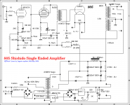
Looking at the feedback to the 805 cathode, it goes to a 100ohm resistor. Is this a funny way of saying 50ohm on each side?
Pretty much. Since it's a floating DC supply, you don't really need a 100R variable in that position. That's used with AC heating for hum balancing.
Has anyone here tried this type of feedback on a large triode? Was it with good results? How will this type of feedback effect impedance?
It's just your basic lNFB: cathode feedback. The 805 is a fairly high-u tube with a highish plate resistance, so lNFB will help get the effective plate resistance down for better woofer damping.
I've used lNFB, though not cathode, with pentode 807s with good results in cleaning up the pentode nastiness.
What kind of feedback did you use or find is best?
I'd like to keep it a short loop after realising the improvement in resolution I had with removing gnfb from the circuit.
I questioned running off the anode of the 805 but to where and how to implement it is hard to find online?
Any help or suggestions are greatly appreciated.
I can post my schematics if you like.
What kind of feedback did you use or find is best?
I'd like to keep it a short loop after realising the improvement in resolution I had with removing gnfb from the circuit.
With 807s, I used parallel lNFB, from the plates back to the second voltage amp. It's a bit more flexible in that you can choose your feedback. With cathode feedback, you take what you get.
I questioned running off the anode of the 805 but to where and how to implement it is hard to find online?
Any help or suggestions are greatly appreciated.
I can post my schematics if you like.
Taking parallel lNFB from the anodes of the 805s is going to be a bit more problematic than with 807s. 805s can run up to 1.0KV+, whereas 807s run ~365V. Even that requires at least 600V coupling capacitors since the AC is imposed on the DC, and rises well above the DC rail. With 805s, you're pretty much stuck with cathode feedback, either taken off the secondary or a special tertiary winding on the OPT for that purpose.
Looking at the feedback to the 805 cathode, it goes to a 100ohm resistor. Is this a funny way of saying 50ohm on each side?
Has anyone here tried this type of feedback on a large triode? Was it with good results? How will this type of feedback effect impedance?
I have an 838 SE amp which is almost same characteristics of 805 except for plate dissipation. Cathord feed back circuit is suited for this kind of high myu triode as the cathord feed back changes characteristics of tube from 838 to 845/ 211.
838 35W SE AMP 2006
Nothing wrong with cathode feedback that I know of, just keeping my options open and trying to learn of the various ways. Is there anything you could think of that would be problematic with it? I'm all ears.
So it seems I will have to reverse phase of the transformer.
Then I suppose it really wouldn't matter what tap I run off of? (probaly 8ohm???)
I could then simply run feedback to the cathode and the two 47ohm resistors automaticaly attenuate the feedback?
I'll also have to lift the ground.
Off hand if anyone could tell me if I'm wrong about the above statments I'd sure appreciate it.
I may try this afternoon.
OK, I was wrong about the TF phase thought it would be like on schematics but mine is not, ie; positive feedback is edgy...anyway I got to try out Cathode FB after a bit of soldering and it did tighten up bass a little but the sacrafice of everything else is defintily not worth it, it was appearant right away, similar to GNFB but not to smear as much. I'm finding SET bass to be kinda relaxing, it's still large and defined but just doesn't have great impact.
BTW 4ohm tap did sound better.
Thanks for the help so far.
BTW 4ohm tap did sound better.
Thanks for the help so far.
OK, I was wrong about the TF phase thought it would be like on schematics but mine is not, ie; positive feedback is edgy...anyway I got to try out Cathode FB after a bit of soldering and it did tighten up bass a little but the sacrafice of everything else is defintily not worth it, it was appearant right away, similar to GNFB but not to smear as much. I'm finding SET bass to be kinda relaxing, it's still large and defined but just doesn't have great impact.
BTW 4ohm tap did sound better.
Thanks for the help so far.
Amount of cathode feedback depends on Mu of output tube and turns of 2nd or 3rd winding coils of OPT.
In my opinion, dumping factor of tube amp should be 1.0 at least.
My OPT has 36 ohm of 3rd winding coil which adapted to 838(Mu of 50) and gets dumping factor of 1.6 with only CFB.
If you don`t want using GNFB, you should use full of your 2nd winding, 16 ohm tap. May be you can get nearly 1.o of DF?
I learned that even CFB with OPT, too much amount of NFB is affects to the sound (too tight).
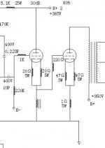
I have tried attached cathode feedback on my 811A SE amp.
An 811A has so high Mu(160) that 36 ohm of 3rd winding seems too much.
With out CFB, dumping factor was 0.2 and with 36 ohm of CFB DF become 2.0.
Schematic 14 shows added 50 ohm of resister in between cathode and 3rd winding coil, functioning current feedback and reduced
dumping factor from 2.0 to 1.5.
Schematic 15 shows using 4 ohm of 2nd winding coil and added
small amount of GNFB and get total DF of 1.0.
Attachments
- Status
- This old topic is closed. If you want to reopen this topic, contact a moderator using the "Report Post" button.
- Home
- Amplifiers
- Tubes / Valves
- schematic question? 805 feedback