Hi, been working on this for a while now and got to the point where I am really happy with result and want to “close the box”.
After trying various drivers settled to 2 options, able to switch between; 5687 and 2c51 in parallel; 5687 sounds better to me at higher listening level while I prefer 2c51 at low volume.
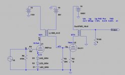
5687 gives me a sensitivity of 1.2V on input to get around 6W in class A1 while 2c51 needs about 0.6V on input, so there is 6 db difference.
At this point I just want to finalize the biasing method for the driver stage. Since I am using input transformer any way, there is a possibility to use fixed bias and connect the cathode straight to ground. I worked out two options, one using resistor divider from my negative supply while second one uses “hybrid” method with NiCd 2.4V batteries providing bias voltage while being charged by negative supply.
I would really appreciate opinions on following:
1) Is there real advantage to use battery version (lover AC resistance to ground)?
2) Classic resistor option gives me better flexibility to dial any bias I want as well as better long term reliability, but is there downside?
3) Is there need for first 0.22uF cap that by-passes from bias supply to ground; I found that 1uF on my output stage made a huge difference, improving both, frequency response and distortion, but not sure if that is same with the first stage?
4) One point that concerns me on battery version is that batteries would discharge while amp is not in use and then charge back up once bias supply is turned on. I do switch my heaters and bias supply before the B+, but am not sure how stable voltage would battery in this configuration provide and how long would they last.
I attached schematics for both versions in PDF as they are easier to read that way.
After trying various drivers settled to 2 options, able to switch between; 5687 and 2c51 in parallel; 5687 sounds better to me at higher listening level while I prefer 2c51 at low volume.
5687 gives me a sensitivity of 1.2V on input to get around 6W in class A1 while 2c51 needs about 0.6V on input, so there is 6 db difference.
At this point I just want to finalize the biasing method for the driver stage. Since I am using input transformer any way, there is a possibility to use fixed bias and connect the cathode straight to ground. I worked out two options, one using resistor divider from my negative supply while second one uses “hybrid” method with NiCd 2.4V batteries providing bias voltage while being charged by negative supply.
I would really appreciate opinions on following:
1) Is there real advantage to use battery version (lover AC resistance to ground)?
2) Classic resistor option gives me better flexibility to dial any bias I want as well as better long term reliability, but is there downside?
3) Is there need for first 0.22uF cap that by-passes from bias supply to ground; I found that 1uF on my output stage made a huge difference, improving both, frequency response and distortion, but not sure if that is same with the first stage?
4) One point that concerns me on battery version is that batteries would discharge while amp is not in use and then charge back up once bias supply is turned on. I do switch my heaters and bias supply before the B+, but am not sure how stable voltage would battery in this configuration provide and how long would they last.
I attached schematics for both versions in PDF as they are easier to read that way.
Attachments
Why don't you just use cathode bias? I've seen NiCd batteries used in place of the cathode resistor but no where else in the circuit. To be honest I've never seen fixed biased small signal tubes. It's just not practical. Maybe I'm missing something. Why do you want the cathodes connected to ground? What you're doing is unnecessary.
Last edited:

Hi!
There are many more factors which contribute to the sound than just the bias scheme. You cannot generally say that one sound better than the other since the whole impelmentation plays a big role. Here my answers/opinions to your questions:
1) Is there real advantage to use battery version (lover AC resistance to ground)?
I see no advantage. It's different. In one case you have a cap in the signal path, in the other case a battery. They are different. One is not necessarily better than the other. If I had the choice I'd prefer a cap.
2) Classic resistor option gives me better flexibility to dial any bias I want as well as better long term reliability, but is there downside?
As has been mentioned above: No real need to use fixed bias. Cathode bias works extremely well and lets the tubes settle at the op point which is best for their emission which is left and the plate voltage. The downside is the bypass cap which is in the signal path which most often is an electrolytic. At your driver I see an electrolytic in the B+ anyways.
I use the ultrapath approach to eliminate the bypass cap from the signal path
3) Is there need for first 0.22uF cap that by-passes from bias supply to ground; I found that 1uF on my output stage made a huge difference, improving both, frequency response and distortion, but not sure if that is same with the first stage?
If your bypass cap makes a big difference, that prooves that the bias supply is in the signal path. Ultrapath with cathode resistor reduces the caps in the signal path down to one (at least for part of the frequency band) and is better controllable IMHO
4) One point that concerns me on battery version is that batteries would discharge while amp is not in use and then charge back up once bias supply is turned on. I do switch my heaters and bias supply before the B+, but am not sure how stable voltage would battery in this configuration provide and how long would they last.
Another argument for cathode bias. Works reliably and adapts automatically as the tubes age. I fussed around with fixed bias too in the path, beeing paranoid about eliminating caps and resistors from teh signal path. Nowadays I am happy with cathode bias
Best regards
Thomas
You also have to worry about the high temperatures inside the chassis which may or may not react well with the battery. NiCd batteries are designed to run hot, but what about ambient temps inside? Morgan Jones has a few examples of coin battery biasing in his book, but why bother.
LED bias is a bad idea, *unless* the stage is CCS loaded:
- Vf and dynamic impedance change with the signal!
- three green leds in series have rather highish impedance
- does not prevent the tube from running away (an increase in idle current is not throttled by the cathode resistor or anode CCS)
- Vf and dynamic impedance change with the signal!
- three green leds in series have rather highish impedance
- does not prevent the tube from running away (an increase in idle current is not throttled by the cathode resistor or anode CCS)
As it happens i have run a 5687 in a preamp in almost exactly the same configuration as shown for years. Briefly tried a CCS and soundwise it presented no benefits compared to transformer or choke load. As for the "highish impedance" of the LEDs or the possibility of the tube running away - well, it didn't run anywhere and it sounded much better than cathode bias. But theorising is great ")
I use fixed bias and batteries extensively in my designs for driver stage duties, but generally avoid Ni-Cad or NiMH batteries in the cathode circuit, preferring battery or negative supply derived grid bias instead. Works well with input transformers or in the case of a power amplifier driven by a line stage with an output transformer which can be floated. (I do this now)
I've used red and infra-red leds for bias and modulation of the small dynamic resistance has been less of a problem IMLE than the colorations imposed by the large electrolytics required for cathode bias with tubes like the 5842/D3A/7788, etc.
On some red leds I measured the vf varied only a few mV from 5 - 20mA forward current, sample to sample variation of vf was well under 20mV for these leds at a fixed current of 10mA.
Using fixed bias without provisions for adjustment may require selection of tubes in order for the circuit to functional optimally. This is a tradeoff I make with some of my designs.
Agreeing with cotdt I prefer fixed bias if for no other reason than the fact it eliminates what is usually a pretty questionable electrolytic capacitor from the signal path. (Small high quality films in the grid circuit IMO do much less damage to the sound) In power stages the ability to easily tune operating point offsets the convenience factor of auto bias (cathode bias) and eliminates that cap I mentioned..
Something I want to mention about battery bias - use alkaline or other non-rechargeable types for grid bias, this will prevent the dead battery zero bias excitement some of my friends have experienced when they did not listen to this bit of advice.. Check the batteries periodically. (Battery life in A1 applications is about shelf life.) Alkalines I generally solder, lithium-iron alkaline AA/AAA and any other lithium types I always use in holders for safety - just check the contacts periodically, probably not a bad idea to apply contact preservative at installation time.
I've used red and infra-red leds for bias and modulation of the small dynamic resistance has been less of a problem IMLE than the colorations imposed by the large electrolytics required for cathode bias with tubes like the 5842/D3A/7788, etc.
On some red leds I measured the vf varied only a few mV from 5 - 20mA forward current, sample to sample variation of vf was well under 20mV for these leds at a fixed current of 10mA.
Using fixed bias without provisions for adjustment may require selection of tubes in order for the circuit to functional optimally. This is a tradeoff I make with some of my designs.
Agreeing with cotdt I prefer fixed bias if for no other reason than the fact it eliminates what is usually a pretty questionable electrolytic capacitor from the signal path. (Small high quality films in the grid circuit IMO do much less damage to the sound) In power stages the ability to easily tune operating point offsets the convenience factor of auto bias (cathode bias) and eliminates that cap I mentioned..
Something I want to mention about battery bias - use alkaline or other non-rechargeable types for grid bias, this will prevent the dead battery zero bias excitement some of my friends have experienced when they did not listen to this bit of advice..
Check the batteries periodically. (Battery life in A1 applications is about shelf life.) Alkalines I generally solder, lithium-iron alkaline AA/AAA and any other lithium types I always use in holders for safety - just check the contacts periodically, probably not a bad idea to apply contact preservative at installation time.I used NiCad batteries as bias in the World Audio Design 2A3 amp.
This was a mod which came out on the long gone forum.
My thought was that NiCad cells loose their charge just sitting "on the shelf"
So if the amp had been switched off for some time and the cells were discharged what was happening?
I changed back to standard Cap & Resistor bias just to stop my brain worrying what happened at switch on.
The amp is still fine with 1940 era British 2A3 valves
1) Is there real advantage to use battery version (lover AC resistance to ground)?
I see no advantage. It's different. In one case you have a cap in the signal path, in the other case a battery. They are different. One is not necessarily better than the other. If I had the choice I'd prefer a cap.
I don't see any advantage of using a battery either. Personally, I wouldn't want the bias to be dependent on a battery that may have discharged since the last use.
As far as the impedance goes, capacitors are very well characterized. At least if you buy one that comes with a data sheet (pretty much any polypropylene cap on Digikey, Solen's caps, etc). You know what you get. With batteries, their internal resistance may be measured, but it's heavily dependent on the state of the battery. Also, I doubt you'll find data for their impedance vs frequency.
Each to their own, but I prefer to know what I'm getting.
As has been mentioned above: No real need to use fixed bias. Cathode bias works extremely well and lets the tubes settle at the op point which is best for their emission which is left and the plate voltage. The downside is the bypass cap which is in the signal path which most often is an electrolytic. At your driver I see an electrolytic in the B+ anyways.
You could eliminate the B+ reservoir cap by connecting the cathode bypass cap from the cathode to B+. This is what Loftin & White did. It reduces the signal path on the output stage to the OPT, output tube, and the bypass cap.
LED bias is a bad idea, *unless* the stage is CCS loaded:
- Vf and dynamic impedance change with the signal!
- three green leds in series have rather highish impedance
- does not prevent the tube from running away (an increase in idle current is not throttled by the cathode resistor or anode CCS)
Three HLMP-3507 green LEDs in series present a dynamic impedance on the order of 40~50 ohm at 10 mA. That's not that high, actually. Especially when it's up against the impedance of the anode load. It'll have a negligible impact on the gain of the input stage and will, if anything, reduce the THD ever so slightly.
~Tom
You could eliminate the B+ reservoir cap by connecting the cathode bypass cap from the cathode to B+. This is what Loftin & White did. It reduces the signal path on the output stage to the OPT, output tube, and the bypass cap.
Yes, the so called ultrapath cap, I mentioned that in my post...
Thomas
Last edited:
I'm at work, so I can find my trusty GEC (and I'm not sure if this is even the right source) tube manual, but there was a discussion of the overload characteristics of fixed versus self-bias.
If I remember correctly, self bias has better overload even though it creates less power, creating the aural illusion of actually making the more power. Again, I could be way off base with this since it has been awhile since I've read the book.
If I remember correctly, self bias has better overload even though it creates less power, creating the aural illusion of actually making the more power. Again, I could be way off base with this since it has been awhile since I've read the book.
Yes, the so called ultrapath cap, I mentioned that in my post...
Oh. I guess I'm not up on the latest GeekSpeek. My bad...
~Tom
- Status
- This old topic is closed. If you want to reopen this topic, contact a moderator using the "Report Post" button.
- Home
- Amplifiers
- Tubes / Valves
- 211 IT amp, battery vs fixed bias