Hi Y'all,
I recently acquired a pair of Wright Audio WPA 3.5 monoblocks, they sound really excellent in stock. However, there was some hum in one of the amps, just a tiny bit more than in the other one, so I decided to investigate...
There are no hum pots on these amps, and also no schematics available online (at least I couldn't find one). One drawing of WPA 3.5 schematic floating on the web is incorrect.
2a3 filaments in this amp are fed from center-tapped filament transformer with CT connecting to the cathode resistor/capacitor. I installed 10 turn 50ohm pot connecting the wiper to the cathode bypass capacitor, cutting the connection to the cathode resistor on top. This way I have the CT of the transformer running to the cathode resistor and humpot wiper - to bypass capacitor. After adjusting the amps are dead quiet, I could detect minute traces of hum with my ear to 95db speakers. This method of connecting the humpot with center-tapped filament transformer was described on this forum site by a kmeier.
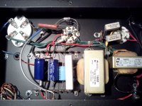
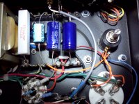
I attached the humpot using hot glue - easy to reverse the changes. You can see the big Xicon 750ohm resistor and small blue 100uf cap with connection between them snipped and bent off.
Attaching pics before and after.
I will post the schematics of the amp as soon as I finish it on TinyCAD. I believe sharing the pics and schematics will serve the owners of these fabulous amps. Sadly Mr. Wright is no longer with us and service of his creations is left to the owners.
I recently acquired a pair of Wright Audio WPA 3.5 monoblocks, they sound really excellent in stock. However, there was some hum in one of the amps, just a tiny bit more than in the other one, so I decided to investigate...
There are no hum pots on these amps, and also no schematics available online (at least I couldn't find one). One drawing of WPA 3.5 schematic floating on the web is incorrect.
2a3 filaments in this amp are fed from center-tapped filament transformer with CT connecting to the cathode resistor/capacitor. I installed 10 turn 50ohm pot connecting the wiper to the cathode bypass capacitor, cutting the connection to the cathode resistor on top. This way I have the CT of the transformer running to the cathode resistor and humpot wiper - to bypass capacitor. After adjusting the amps are dead quiet, I could detect minute traces of hum with my ear to 95db speakers. This method of connecting the humpot with center-tapped filament transformer was described on this forum site by a kmeier.
I attached the humpot using hot glue - easy to reverse the changes. You can see the big Xicon 750ohm resistor and small blue 100uf cap with connection between them snipped and bent off.
Attaching pics before and after.
I will post the schematics of the amp as soon as I finish it on TinyCAD. I believe sharing the pics and schematics will serve the owners of these fabulous amps. Sadly Mr. Wright is no longer with us and service of his creations is left to the owners.
Attachments
Last edited:
The listening test results are in...Installing humpot solved problems associated with hum balancing but affected the sound quality in a negative way. The sound lost some of its brilliance and detail, sucking the soundstage into the speakers. Humpots - out.
For now I am keeping these excellent amps stock.
For now I am keeping these excellent amps stock.
You had the entire current for the 2A3 going through the wiper of the hum pot. See the attached schematic for an alternative method: the current from the cathode resistor goes through 15 ohm resistors to each side of the hum pot. These resistors carry most of the current. Another point is the hum pot itself. You don't need a 10 turn pot; what you need is a robust pot. I use a PEC 2W.
Attachments
There's definitely an audible difference in the way the cathode is wired and the AC is balanced. I suspect that long taper 10 turn pot is not suitable here, or maybe it's the way I used the pot together with the filament transformer center-tap, creating two different signal paths that resulted in signal smear. Whatever the case the G.R. method seems to be the best.
Another thing to try is Tentlabs DHT filament supply, but in this case those modules would not fit into the chassis. I used Tentlabs modules on my other amps with excellent results.
Another thing to try is Tentlabs DHT filament supply, but in this case those modules would not fit into the chassis. I used Tentlabs modules on my other amps with excellent results.
I am a bit cautious around the stock power cords in the WPA's, - having non-grounded chassis is theoretically dangerous. I would suggest just replacing the cord with a good quality grounded cable, without installing IEC chassis plug.
I didn't finish the schematic. As I was working on it my kid took the "blueprint" and made it into an airplane, or a boat, or maybe spiderman mask...As I am still working on these amps I will re-create the schematic.
There is one schematic that is floating on the web, it has a major mistake there though, in the power supply section - the choke should be on the negative side, not positive. Some other values and connections are a bit off. On the original there is no hum pot (it uses center tapped filament transformer on the secondary)
An externally hosted image should be here but it was not working when we last tested it.
Last edited:
The numbers on my Wright 3.5's power transformer are DMI 500-7694 with a "0050" written really small under them manufactured by DeYoung Mfg. (deyoungmfg.com). The company is in Washington I assume close to Kent where amp was made. The serial numbers on my amps are 006R and 006L. I don't know if that means they were actually made that early.
Another plug for that schematic. What would fix the choke on the incorrect one posted?
Another plug for that schematic. What would fix the choke on the incorrect one posted?
According to some posts DeYong custom power transformers were used on later builds of WPA 3.5 amps. My amps are #405L/R and those ps transformers look like Hammond 200 (272BX?)series.
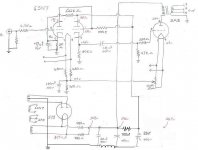
On the schematic above, in the power supply section the first cap is 22uf, second - 100uf, third - 22uf. The 2K (2.05K on schematic) resistor should be between the 100uf and third 22uf caps. The last 10uf cap does not exist. The choke should be between negative terminals of first 22uf and 100uf with the left side connecting to the CT of power transformer secondary. There is no "traditional" grounding on these amps.
Attached is my approximate "rendition".
Attachments
Last edited:
Removing both cathode bypass capacitors from Wright 3.5
I am seeking advice on removing both the cathode bypass capacitors from the 2A3 and 6SN7 tubes. The 100uf cap for the 2A3 and 47uf cap for the 6SN7. First is to confirm the 47uf is the 6SN7 cathode bypass cap? I would like to reduce the gain in my Wright 3.5 amps which are driving my 111db HF drivers. The MF drivers are 100db efficient so I would be able to use less attenuation in my active crossover. And if there will be less distortion that would be a great byproduct.
I am seeking advice on removing both the cathode bypass capacitors from the 2A3 and 6SN7 tubes. The 100uf cap for the 2A3 and 47uf cap for the 6SN7. First is to confirm the 47uf is the 6SN7 cathode bypass cap? I would like to reduce the gain in my Wright 3.5 amps which are driving my 111db HF drivers. The MF drivers are 100db efficient so I would be able to use less attenuation in my active crossover. And if there will be less distortion that would be a great byproduct.
I would like to reduce the gain in my Wright 3.5 amps
Simply replace the fixed grid resistor of the first 6SN7 stage with a 100k pot. You can replace the 4.7k grid stopper with 1k.
You can't remove the 100uF cap on the 2A3 cathode resistor; what you need to do is put a very good cap there like a motor run. The 47uF cap on the first stage cathode shouldn't be there, I would think. It seems to shunt the feedback to ground. I would check the schematic against your amp and see what's really there.
Thank you for the suggestion. I have already replaced the 100uf cap with a 50uf ASC motor run. I would like to avoid adding something else or something possibly worse in the signal. I have read many posts here and there about lower distortion benefits of having no cathode bypass caps with the drawback being less gain. Is there something special about the 3.5's circuit that would prevent this?
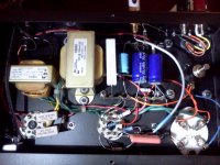
The 47uf cap which I believe is the 6SN7 bypass cap is in the fourth picture down in the first post in this thread. It is the little black cap just to the left of the brown coupling cap below the cathode resistor. It is light blue on my amp.
Thank you, Mike
The 47uf cap which I believe is the 6SN7 bypass cap is in the fourth picture down in the first post in this thread. It is the little black cap just to the left of the brown coupling cap below the cathode resistor. It is light blue on my amp.
Thank you, Mike
Removing bypass caps from Wright WPA 3.5
I did try removing both cathode caps and it resulted in a 9 or 10db reduction in gain. This would have been perfect but it also resulted in a constant 60hz Hum easily heard from the listening position as well as nearby rooms. Bob From Florida over at the hawthorne Audio Forum explained it this way:
"Put the 100 uf cap back in the circuit and the hum should go away. What they were trying to do was put a DC reference on the AC filaments for the 6SN7 using the bias current from the 2A3 through the 750 ohm resistor. Putting AC filaments at a DC level often quiets things down a bit. The problem with the circuit drawn is if you remove the cap you lose the fixed DC level at that point. Any level shifting between the two differing filament voltages will get amplified through the cathode of the 2A3 - remember the cathode and the heater are directly connected on a 2A3."
When I added back two 27uF caps back to the 2A3 cathode the hum went away and the gain did remain decreased about 3db which allows me to hold the HF crossover dial at 0db and MF dial at plus 6db. This helps.
Out of interest I took out my Fluke and measured the voltages throughout the amp, on both of them. Measurements were done with 8 ohm dummy load on output. Here are the results for Amp 1 and Amp 2:
AC mains: 124V
PT output: 683V and 685V CT
AC Filaments:
5Y3: 5.5V and 5.52V
6SN7: 7.2V and 7.32V (ouch!)
2A3: 2.78V and 2.8V (really bad)
DC voltages:
2A3 plate: 308V and 308.7V
2A3 cathode: 47V and 47.5V (that makes ~261V plate to cathode)
6SN7 top triode plate: 304V and 303V (a tad over 300V, but it should live)
Filament AC voltages are quite beyond "excessive" and need to be dropped. I ordered some low value resistors for this purpose. I also plan on changing power transformers to modern ones with 120V or 125V primaries. Current PT are Hammond (I think 272X) with 115V primaries only.
If you are the owner of one of these wonderful amps I would suggest measuring your filament voltages and adding dropping resistors for your tubes' sake. It would need ~1.5R for 6SN7 heaters in parallel (2x0.68R would do), and 0.12R for 2A3 (0.1R should be fine).
Last edited:
- Status
- This old topic is closed. If you want to reopen this topic, contact a moderator using the "Report Post" button.
- Home
- Amplifiers
- Tubes / Valves
- Wright Audio WPA 3.5 Humpot & schematics