Thanks for all your comment guys...
@Jazbo...I can't see the picture you attached...i hope you drawn your loadlines for me to refer...I greatly appreacite it... kindly re attach the picture...
Okay guys...how about reducing the OPt impedance to 5k by making the 16ohm secondary for 8 ohm speaker...does it make sense?...i just dont know if the opt can handle the primary current needed and how it will affect the bandwith?.
just build your amp and find out, your idle bias determines your drive requirements....i wouldn't worry too much about your output stage, you are not stressing your GU50 that much....
besides we do not yet know how much your psu will sag once you have biased your output tubes to about 60 mA, is that per tube or per tube pair?
if per tube, that is a whopping 240ma of idle current draw, the question then becomes, how capable is your power traffo in supplying this amount of power, remember that that was used on a peanut tube...
@jazbo...still I can't open your attachment...maybe convert it to pdf or jpeg file.
yes i'm trying to compute again base on 5k load... my power trafo has 2 x 350vac and i will use FW silicon diode rectifier for B+ of around 450vdc. i will not use the 5U4g which only give around 320Vdc.
I will try to approximate the power rating of the amp to suit the opt around 15w-20w .Currently the opt is running at 44ma idle for each plate for the 6BQ5's.What will be the best bias current for this to start...any suggestion?
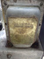
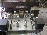
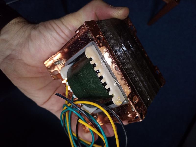
I had attached the power trafo and Opt pix..
yes i'm trying to compute again base on 5k load... my power trafo has 2 x 350vac and i will use FW silicon diode rectifier for B+ of around 450vdc. i will not use the 5U4g which only give around 320Vdc.
I will try to approximate the power rating of the amp to suit the opt around 15w-20w .Currently the opt is running at 44ma idle for each plate for the 6BQ5's.What will be the best bias current for this to start...any suggestion?
I had attached the power trafo and Opt pix..
Attachments
Last edited:
just build your amp and find out, your idle bias determines your drive requirements....i wouldn't worry too much about your output stage, you are not stressing your GU50 that much....
besides we do not yet know how much your psu will sag once you have biased your output tubes to about 60 mA, is that per tube or per tube pair?
if per tube, that is a whopping 240ma of idle current draw, the question then becomes, how capable is your power traffo in supplying this amount of power, remember that that was used on a peanut tube...
Sir,that will be per pair i hope, as based by the computation of turner audio.
@jazbo...still I can't open your attachment...maybe convert it to pdf or jpeg file.
It is not an attachment, it is a link on a file storage facility that don't give it to some subnets because probably there were infected computers in that subnets. He can save it on a local drive then attach.
the question then becomes, how capable is your power traffo in supplying this amount of power, remember that that was used on a peanut tube...
I agree, not sure if the PT is upto the task, and 20W is really too small for GU50 PP, they are not even breaking a sweat... Surely, it would be easier to just to get some replacement tubes and be done with it, and do another project that's worthy of the GU50.
")
BTW, the file is already jpeg, not sure how to up load a local file directly to the forum... try this link >> https://dl.dropbox.com/u/1326040/GU-50%20PPT_400.jpg
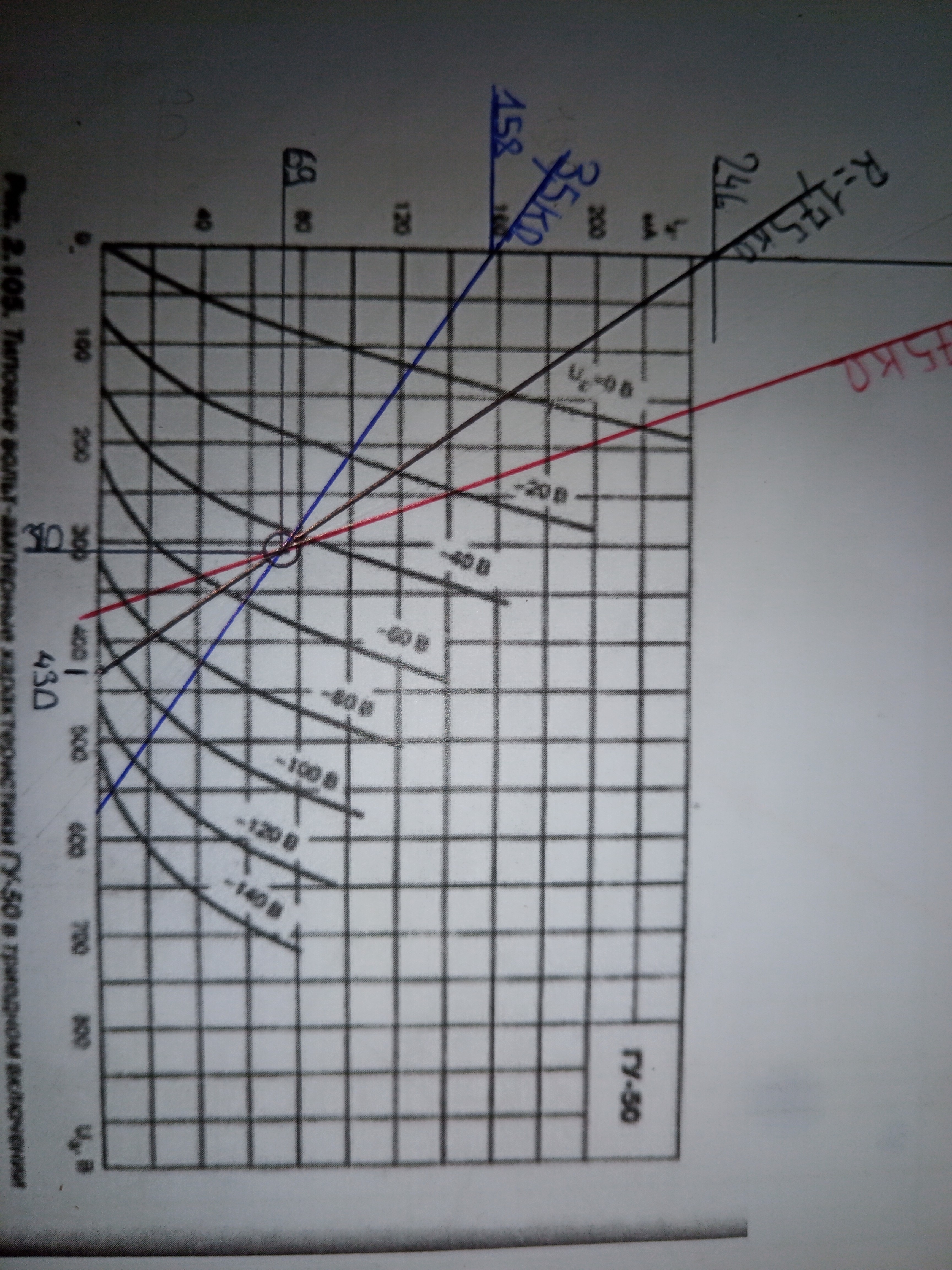
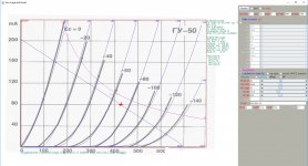
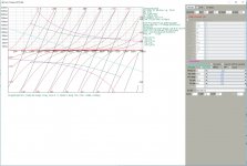
too sad,.. i have plenty of gu50 to use, but seems not fitted for my available opt.. i have other projects of gu-50, a 50w amp in pentode mode....that's why i'm trying it triode mode this time using the same tubes if possible too. I'll try to make it 5k load and see..
anybody has other pp triode schematics for reference?
anybody has other pp triode schematics for reference?
Hi,
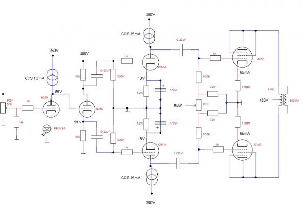
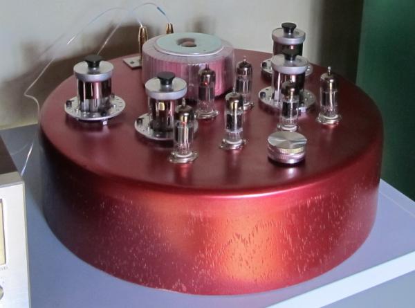
this is my PP version with GU50 in triode. For input/splitter I used 6350 (like 12AU7) and for driver 12B4A. I get around 14W.
Hello ,
I use will use the same load 3,5k and the same configuration :
Gu50 triode strapped Push-pull.
Voltage supply will be 430v regulated.
I'm afraid for my transformers.They are 50w transformers,iron is 86*72*50.
I don't know the max current they can handle.
Please what is your max current at one anode ?
Regards
Thanks for early reply.
Only !??
Is it the Operating point ?
Do you have :
Ua max=430v ?
I don't understand anything more .
For me:
Can you explain to me, please ?
It was 80-85mA
Only !??
Is it the Operating point ?
Do you have :
Ua max=430v ?
I don't understand anything more .
For me:
Can you explain to me, please ?
The 'screen stopper' resistor is usually put in series with the screen grid to suppress oscillation. It may also help to subdue overheating of the screen grid during sustained loud passages where screen grid dissipation limits may be reached.
The screen stopper resistor is not strictly necessary, but it is a good precaution to take.
--
The screen stopper resistor is not strictly necessary, but it is a good precaution to take.
--
Hello Rongon,The 'screen stopper' resistor is usually put in series with the screen grid to suppress oscillation. It may also help to subdue overheating of the screen grid during sustained loud passages where screen grid dissipation limits may be reached.
The screen stopper resistor is not strictly necessary, but it is a good precaution to take.
--
I have a packet of 220 Ω 3W metal film resistors?
Will they do the job please ?
Hello.And for PP:
The power at anode is 34,9w. Gu50 max power is 40w.Did you have any problem with your tubes ?
Regards
- Status
- This old topic is closed. If you want to reopen this topic, contact a moderator using the "Report Post" button.
- Home
- Amplifiers
- Tubes / Valves
- GU-50 PP + 10k:16-8-4 Ohm ,20w OPT..what is the best to do?