Hello,
I have successfully built 2 single ended tube amps using the Powerdrive MOSFET source follower into Eimac 35t tubes with positive bias. This works great. On the data sheet, it says that the max signal driving power for the 35t near my operating point is 7 watts.
I have been playing with the Eimac 100TH using the same circuit. While I can get the tube to play loudly, there is a bit of distortion. The 100TH max signal driving power rating is close to 20 watts. It seems that my IRF820 MOSFET biased at 7.5 watts is not cutting the mustard.
Is the solution to crank up the MOSFET bias to 35 watts (it is a 50 watt part) or do I need to use a larger MOSFET? Does this sound like the problem? The output transformer is the big single ended Hammond (6.5K) with an 8 ohm speaker on the 4 ohm tap.
Thanks
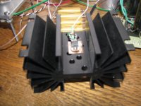
So, I cranked up the current on the IRF820 and the distortion on the 100TH went away. I am running the IRF820 at 50mA and 19 watts dissipation. The fairly large heatsink gets pretty hot, hotter than you want to keep your hand on for more than 5 seconds. Is it safe to assume that the ability of the source follower to drive the grid is only a function of the mA the MOSFET is running, not the dissipation of the part?
You should take SOA or Safe Operation Area into account, see IRF820 datasheet. Basically the SOA diagram describes drain current - drain:source resistance in ON state and pulse width as parameter. Next thing you should consider is thermal condition of mosfet operation i.e. pick proper radiator which ensures junction temperature is not exceeded.
Sorry if this sounds a bit obvious and possibly totally wrong, but couldn't you drop the voltage on the IRF820 and up the current to keep the heat down. even if you used a power resistor to take some of the load. After all, these components are capable of running at amps of current and they are generally more linear (not an issue here) the higher the bias current.
Just a thought.
Shoog
Just a thought.
Shoog
Some pics
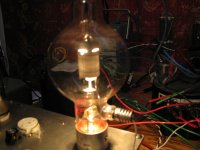
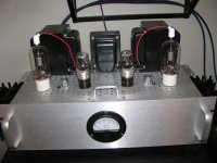
Yes, I will drop the drain supply from 350 to 100v. The pictures include my completed 35t amp. Thanks.
So as long as there is sufficient current and voltage headroom to cover the AC signal, increasing the dissipation does nothing but increase heat?
Yes, I will drop the drain supply from 350 to 100v. The pictures include my completed 35t amp. Thanks.
So as long as there is sufficient current and voltage headroom to cover the AC signal, increasing the dissipation does nothing but increase heat?
Attachments
Correct.Yes, I will drop the drain supply from 350 to 100v. The pictures include my completed 35t amp. Thanks.
So as long as there is sufficient current and voltage headroom to cover the AC signal, increasing the dissipation does nothing but increase heat?
Shoog
Yes, I will drop the drain supply from 350 to 100v. The pictures include my completed 35t amp. Thanks.
So as long as there is sufficient current and voltage headroom to cover the AC signal, increasing the dissipation does nothing but increase heat?
I like this vintage meter in contrast to modern industrial aluminum chassis. Great!
alternative mosfet
Hello
One of our customers plans to use a AOT1N60 mosfet for A2 drive. This one has nice specs and a substantially lower input capacitance. Perhaps this could be a nice alternative. Nice project!
I am using tubes to drive the grid of an 833A or the TB3/1000 European equivalent as can be seen on mu 150W SE amp blog.
Kind regards, //WDC
www.monolithmagnetics.com
So, I cranked up the current on the IRF820 and the distortion on the 100TH went away. I am running the IRF820 at 50mA and 19 watts dissipation. The fairly large heatsink gets pretty hot, hotter than you want to keep your hand on for more than 5 seconds. Is it safe to assume that the ability of the source follower to drive the grid is only a function of the mA the MOSFET is running, not the dissipation of the part?
Hi,
building a 100TH amp myself.
can you post the diagramm?
thanks
Hi FET drivers,
I'm driving min 211 amp by IRF820, I run 30mA amps in the FET @ app 5W.
Remember to have 50V head room in both ends of the sine.
Best regards
Karsten
Hi, I have built during winter 2015/16 a 2x 211 PP-amp which uses a PL508 as cathode follower (grid of the 211 directly at the PL508 cathode) and current driver for the 211. PL508 running with about 220V and 50 mA plate current. 211 plate voltage about 720 - 740 V.

I am not seeing how this works. Do you have a schematic?
The original PowerDrive design was presented here:
Power Drive | Tubelab
It's implementation in an 845 SE amp is shown here, scroll down to the third schematic:
845 SE | Tubelab
I used the same 845 amp to "breadboard" a temporary mono amp using an 833A. The 845's were removed and an 833A was wired into one channel with clip leads. It was soon obvious that the 845's power supply wasn't up to feeding an 833A, so the power supply out of a radio transmitter was wired in. It is shown here:
833 SE | Tubelab
use MOSFET to drive speaker .why not ?
It is possible to use a tube driver setup with a mosfet output stage to DIRECTLY drive a speaker. You will find "hybrid" designs scattered throughout these forums, and most are of this type. In my rather limited experience it will work, but not sound like a tube amp.
The tube driver stage is capable of providing plenty of drive voltage, more than you need for driving a speaker of normal impedance (4 to 16 ohms). You could use this to drive a CCS loaded mosfet follower in class A, or a typical complementary pair output stage to generate the needed current to feed the speaker. I have built a couple amps this way, and they sounded more like a typical solid state amp than a typical tube amp.
You can build a low powered tube amp, then directly couple the plates of the output tubes to mosfet or BJT followers in a manner similar to darlington pairs to boost the current capabilities of the tubes. Then feed this into a tube OPT with a much lower impedance than the tubes would normally drive. This way you can build a higher powered amp and reduce the complexity of the OPT, but there are no real cost savings.
Note, be careful of SOA limitations of the output devices when doing this, especially with BJT's. I blew up several silicon based life forms experimenting with this. The OPT can kick back a lot of voltage when driving a real speaker and pushed into clipping......POOF!
Does sound real nice with serious authority when it works though. I believe that the BJT version sounded the best, but blew up a lot, and since I no longer work for Motorola, silicon is no longer free!
- Status
- This old topic is closed. If you want to reopen this topic, contact a moderator using the "Report Post" button.
- Home
- Amplifiers
- Tubes / Valves
- Powerdrive for higher grid wattage A2 transmitter tubes