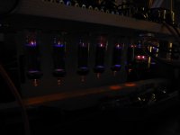
but my OB3 glows orange instead of blue, /gutted/
Well you can't have everything.
") Are those 6080's in the PS picture?
Are those 6080's in the PS picture?jeff
Yes two 6080 tubes using two triodes from one tube and another triode from the second tube in Parallel to regulate the power the output stage, the spare triode on the second 6080 is used in a series regulator to power the preamp stage (output is 300volts preamp is 260 volts). The power stage regulator has an OB3 in it, the preamp stage regulator has an OA3 in it.Well you can't have everything.
jeff
What is not shown is an EABC80 tube rectifying the output audio signal and amplifying it, to drive an EM800 magic eye indicator, this circuit is powered from an OC3 and OD3 in series to create a regulated 250volt supply.
So in total the amp has the following tubes per channel:
PSU
2 x 6080
2 x 6SL7G
OA3
OB3
OC3
OD3
Amplifier:
8 x EL95
1 x ECC83
Indicator:
1 x EM800
1 x EABC80
Thats a lot of glass,
Well, I finally gave up trying to get my 20Watts out of this circuit, so I replaced the EL95 tubes with 6005W (same socket and wiring) which a 6AQ5W or EL90 tubes.
With a little re-biasing I got nearly 22 Watts RMS out of it, and a nice blue glow to suit.
The amp draws a steady 240mA from the B+ peaking at 270mA for high volume. Currently I have two silicon diodes in the rectifier and a sing 400uF smoothing capacitor before the regulators, there is no hum or buzz whatsoever. Being a valve purist I thought I might replace the silicon diodes with a pair of impressive EY500 damper diodes (440mA each max). 400uF is probably too much filter capacitor even for these big diodes. I don't want to have to put a choke in, and I have plenty of reserve HT voltage on other windings available. Can anyone suggest a solution, eg: silicon diodes across the EY500s with a resistor to "precharge" the capacitor maybe??
Sorry; going a little retro here,
Careful here, Ian - this is in pentode according to my datasheet. 43% UL taps will not let the anode get much lower than 90V according to my data.
But glad that the problem has been solved. Thus: To check them OPT connections with an ohmmeter before assembling!
EL95 saturation voltage will be around 40V
So should be able to swing 289 - 40 = 249 volts at the anode
or 2 x 249 = 498V pk-pk across the full primary
Careful here, Ian - this is in pentode according to my datasheet. 43% UL taps will not let the anode get much lower than 90V according to my data.
But glad that the problem has been solved. Thus: To check them OPT connections with an ohmmeter before assembling!
Johan,
Thanks - it is quite valuable to have things like this corrected. I will remember it next time and as I use Ultralinear a lot, this is good to know, I had not actually thought about how the UL connection might influence saturation voltage.
Meanwhile no-one gets led astray by bad advise.
Cheers,
Ian
Thanks - it is quite valuable to have things like this corrected. I will remember it next time and as I use Ultralinear a lot, this is good to know, I had not actually thought about how the UL connection might influence saturation voltage.
Meanwhile no-one gets led astray by bad advise.
Cheers,
Ian
Just brain storming your problem, reproduced here for comment:
2500:8 => Impedance ratio of 312.5
Turns ratio is therefore 17.7
20V pk to pk at secondary means 20 x 17.7 = 354V pk-pk across full primary
That is 177V pk across each side of the push pull.
With 300 rail you should be able to get:
300 -11 V at cathode gives 289 across the tube.
EL95 saturation voltage will be around 40V
So should be able to swing 289 - 40 = 249 volts at the anode
or 2 x 249 = 498V pk-pk across the full primary
Which would give 498/17.7 = 28.1 V pk-pk across the 8 Ohm secondary or 9.9V RMS or 12.3 Watts into 8 Ohms maximum.
I think that 300V rail is too low but even with 300V you should be getting 28 volts pk-pk at the secondary before clipping.
Cheers,
Ian
No,no,no!!
You get a swing of 249V on the anode already at 289V.That gives a swing from 289-249=40V to 289+249=538V,a total of 538-40=498V (same as 2x249).So far ok,but the same,in opposite direction on the other side,total swing over Raa 2x498=996V.Back to the sec.996/17.7=56.2V pk-pk ! That's (56.2/2)x0.7=19.6Vrms.Power on 8ohm, (19.6x19.6)/8=48W ,that's better
.With UL somewhat less.
So if everything else is ok the OPT doesn't have the right ratio.
Mona
Last edited:
Mona,
The output transformer has the right ratio, I have measured it, an EL95 in UL push pull with give around 5 Watts RMS, so four pairs in Parallel push pull should give up to 20Watts RMS, the theoretical maximum is in indeed as you have suggested would be closer to 48watts which is why I spec'ed a 40W OPT.
However, The reason I am only getting around 14 watts is because I am running out of current, the amplifier cleanly clips at 30volts peak-peak on the secondary, which is about 12 watts RMS.
A re-bias and substitute for some EL90 tubes (double the anode dissipation of the EL95) gives me over 20Watts RMS in the same circuit.
I think probably I am running the tubes too far into Class A to get any more than this, the EL90s are biased around 30mA a piece which is the maximum dc current my opt transformer will take....this is around 20volts on the cathode compared too 10volts on the EL95.
I would like some more power, but the EL90s (6AQ5W or 6005W) sound really nice at this bias point and 25 watts is enough for now.
I guess if I lower the DC bias current to go closer to cut off I will get more swing and more AB than class A and a bit more power.... any advice is welcome here..
Rethink---
Raa is anode to anode at 17.7 ratio to the speaker.
not 17.7 per side, so I reckon it probably isn't 48Watts after all....
Anyone want to throw a curve ball here and sort this out...
Yes,and there is also a swing of allmost 500V on both sides in opposite fase,that's 1kV between anodes.So ...
Mona
No,no,no!!
You get a swing of 249V on the anode already at 289V.That gives a swing from 289-249=40V to 289+249=538V,a total of 538-40=498V (same as 2x249).So far ok,but the same,in opposite direction on the other side,total swing over Raa 2x498=996V.Back to the sec.996/17.7=56.2V pk-pk ! That's (56.2/2)x0.7=19.6Vrms.Power on 8ohm, (19.6x19.6)/8=48W ,that's better
With UL somewhat less.
So if everything else is ok the OPT doesn't have the right ratio.
Mona
If I understand correctly, you are finding a swing of 249V either side of a center tap at a fixed 289Vdc on one half of the primary, and the same swing on the other half of the primary, only 180 degrees out of phase. The common center tap remains at fixed a.c. potential of zero volts, thus the maximum Vp-p can only be 498V anywhere, not twice that value.
If I understand correctly, you are finding a swing of 249V either side of a center tap at a fixed 289Vdc on one half of the primary, and the same swing on the other half of the primary, only 180 degrees out of phase. The common center tap remains at fixed a.c. potential of zero volts, thus the maximum Vp-p can only be 498V anywhere, not twice that value.
Agreed, however swapping EL90s gives me 25Watts RMS straight out the box, which is 14.2vrms before clipping, this is doing my head in as that is not possible from the voltage numbers we just discussed... at 500v pk-pk
Ok, here is the neartly finished prototype...
6005W (EL90 or 6AQ5W) Parallel push pull prototype - YouTube
300v regulated supply using 6AS7G tubes and OA3/OB3 reference tubes is ROCK steady even at 250mA output stage current draw...
very please..
thanks everyone!
6005W (EL90 or 6AQ5W) Parallel push pull prototype - YouTube
300v regulated supply using 6AS7G tubes and OA3/OB3 reference tubes is ROCK steady even at 250mA output stage current draw...
very please..
thanks everyone!
Well finally, traded up the EL90 (6AQ5) tubes for eight parallel push pull 6v6 tubes, got 42 Watts over 20Hz to 20KHz
I will start a new thread because I have some other questions...
Parallel 6V6 Prototype Amplifier - YouTube
I will start a new thread because I have some other questions...
Parallel 6V6 Prototype Amplifier - YouTube
I am confused by thread was it EL95's or 6aq5's/EL90's ????
looking for EL95 data sheets in english ??
shouldnt 8 push pull 6v6s be 160 watts or so ?
or 80 stereo ? heck we bench tested my Mc Intosh MC75 at 225 watts but distortion rises up a bit . Need a source for the mc output transformers lol .....copy franks rube goldberg winder bill
looking for EL95 data sheets in english ??
shouldnt 8 push pull 6v6s be 160 watts or so ?
or 80 stereo ? heck we bench tested my Mc Intosh MC75 at 225 watts but distortion rises up a bit . Need a source for the mc output transformers lol .....copy franks rube goldberg winder
billThis one is in multiple languages.looking for EL95 data sheets in english ??
- Status
- This old topic is closed. If you want to reopen this topic, contact a moderator using the "Report Post" button.
- Home
- Amplifiers
- Tubes / Valves
- EL95 Parallel Push Pull design