The GreenValve use the 828 Triode as driver and a battery PSU:
Greenvalve Audio Luddite Maxim GM70 Monoblocks - YouTube
Seems there is a Interstage trafo:
A low voltage GM70 / ??70 amp GREENVALVE AUDIO
Greenvalve Audio Luddite Maxim GM70 Monoblocks - YouTube
Seems there is a Interstage trafo:
A low voltage GM70 / ??70 amp GREENVALVE AUDIO
P.S.: A local hobbist tested various drivers tubes and told to me the 6J9P(E180F) when used as Triode is a better sound than the 6N6P, much more detailed.
He also like the EF184 as Triode.
I wonder why builders like use Pentodes straped as Triodes to Drive?? Maybe hi Transcondutance??
He also like the EF184 as Triode.
I wonder why builders like use Pentodes straped as Triodes to Drive?? Maybe hi Transcondutance??
P.S.:
He also like the EF184 as Triode.
Yes, and I used 6J51P in triode mode driving Gu-50 in last Pyramid prototype.
I wonder why builders like use Pentodes straped as Triodes to Drive?? Maybe hi Transcondutance??
In the previous Pyramid I used 6P15P as pentodes, in the same position to drive Gu-50.
I can't tell which is better, both worked equally well. In both cases I used nested fedbacks, including from anodes of Gu-50 to anodes of driver tubes.
Lukasz uses the 6N6P as a cathode follower to drive the GM70. Which is a different application. Enzo is looking for a single tube which can do it all. I.e. provide gain and drive. The Lampizator uses the 6N6P essentially just for the "drive".So, how Lampizator do it??
MALPA a owner of this Lampizator GM70 amp informed the sound quality is great:
Ops I missing this important detail, Thanks.Lukasz uses the 6N6P as a cathode follower to drive the GM70. Which is a different application. Enzo is looking for a single tube which can do it all. I.e. provide gain and drive. The Lampizator uses the 6N6P essentially just for the "drive".
In this case seems only a pentode will do this herculean task.
Hi again,Lukasz uses the 6N6P as a cathode follower to drive the GM70. Which is a different application. Enzo is looking for a single tube which can do it all. I.e. provide gain and drive. The Lampizator uses the 6N6P essentially just for the "drive".
I wonder if Cathode Follower is the same circuit named Mu Follower??
Thanks
So, how Lampizator do it??
MALPA a owner of this Lampizator GM70 amp informed the sound quality is great:
Lampizator GM70 amp
Wow, the Lampizator guy GLUED the capacitors to the top plate. And he is asking 4000€+tax for that mess!

The top element of a tube mu follower is a cathode follower ac coupled to a normal triode stage beneath it, but with a load resister and cathode follower bias resistor between them. R load to the bottom tube is ~top tubes mu x load resistor and R out is ~ 1/gm of top tube, same as cathode follower. you could use a dc cathode follower after the gain stage and do without a coupling cap but the gain stage then doesnt have the high load impeadance and thd goes up. i suppose you could have a ss ccs on first tube and dc couple to a cathode follower..?
Or use a gyrator and take the mu output
enzo
Or use a gyrator and take the mu output
enzo
i suppose you could have a ss ccs on first tube and dc couple to a cathode follower..?
Or use a gyrator and take the mu output
enzo
A Mosfet CCS also has mu output capability... and, compared to the gyrator, there is one less capacitor in the circuit.
OK, Thanks Bro.The top element of a tube mu follower is a cathode follower ac coupled to a normal triode stage beneath it, but with a load resister and cathode follower bias resistor between them. R load to the bottom tube is ~top tubes mu x load resistor and R out is ~ 1/gm of top tube, same as cathode follower. you could use a dc cathode follower after the gain stage and do without a coupling cap but the gain stage then doesnt have the high load impeadance and thd goes up. i suppose you could have a ss ccs on first tube and dc couple to a cathode follower..?
Or use a gyrator and take the mu output
enzo
I found more info here:
How to design valve guitar amplifiers
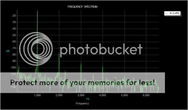
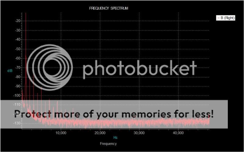
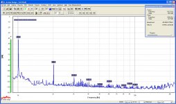
I tried several 6AQ7s tonight. All ran pretty much the same. At 1mA the distortion bests the 6SL7 by about 5dB at all harmonics, and the 6SN7 by about 10dB. Although, the 6SN7 harmonics decreased the most rapidly and I suspect this is in part why it is liked.
Output was 33.6Vrms, and the plots are compensated to set the fundamental peak at 0dB ref (based on calculations). I still haven't figured out how to compensate for the twin T notch filter of the fundamental. Once I do I should be able to get better measurements.
Unfortunately the distortion of the 6AQ7 goes up rapidly when biased above 2.5mA. at 2.5mA the 2nd is up to -64dB with about .08%thd. By 3mA they are terrible with 2nd at -41.9, 3rd -58.9... (0.1%thd).
Although, in the grand scheme of things I guess 0.1%thd when driving a 6A3 to clipping isn't that significant.
Attachments
6AQ7 at 1mA, 2.8Vrms out
Test was with a Gyrator, but not taken from the mu output. The anode of the tube under test was buffered by a MOS FET Source Follower in order to drive the capacitive load of cables between TUT and Twin T filter.
Here is the 6AQ7 biased at 1mA with 2.8Vrms out. 0dB ref is 2.8Vrms. The notch in the Twin T filter is about -43dB, hence the fundamental is at -43.
Attachments
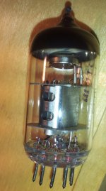
Anyone try 6ZH11P-E
I once popped them in as a pentode driver for my 300b. I liked them. And they look very sturdy. I also tried them as the top tube to replace a d3a in a mu-follower with 6n1p as driver tube. I thought it sounded better than with the d3a in that position. Then again I was probably fooling myself. As I could hardly hear a difference.
I once popped them in as a pentode driver for my 300b. I liked them. And they look very sturdy. I also tried them as the top tube to replace a d3a in a mu-follower with 6n1p as driver tube. I thought it sounded better than with the d3a in that position. Then again I was probably fooling myself. As I could hardly hear a difference.
Last edited:
I have some 6n11p on there way but no zh, presume they're different? Tempted to do some tests to see how much juice some of these anodes and grids can take before they glow. Not suggesting they should be run like that but some of these high gm tubes like there ma's and might be interesting considering their price
Enzo
Enzo
- Status
- This old topic is closed. If you want to reopen this topic, contact a moderator using the "Report Post" button.
- Home
- Amplifiers
- Tubes / Valves
- gm70 driver tube tests