Hi,
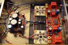
Im looking for some tips on using the Audioromy FU-29 amplifier. I just got one in the mail the other day and powered it up for the first time. Awesome! Sounds great and runs quite silently. However... the day old problem of one of the plates inside the output tubes started to 'red-plate' after 40 minuets of running. I wasn't even running them loudly at all. I turned off the machine and let them cool down for a bit. Turned it on and within another 40 minuets, the one anode started to gently glow red again. All the other plates were happy looking.
So in an effort to double check all the calibrations, I flipped it over to check if the output was balanced (by metering each plate to each channel together). Pretty darn close, about 0.3v off on both channels. But the real question is where do I meter to check the cathodes of each channel? The manufacture requests that the shared cathodes are biased to 0.5v off of ground. So where do I meter? (check out my photos because the new circuit layout is not the typical one seen on previous posts) I tried checking Pin 4 to ground, and its not showing me results I am looking for.
Also, I have 2 convenient GU-29 tubes ready to go if red plating means absolute failure, but if I do install a GU-29, I want to make sure I bias them correctly so that damage wont happen in the future. Does anyone have any tips?
Attachments
If I remember correctly, these dual tetrode tubes are notorious for for imbalance in bias specs between tube halves. They were meant for class B/C operation where matching is not important. Your best bet would be to swap out the tube that is red-plating - hopefully the replacement won't be just as bad.
I was fairly gung-ho about building an amp with 829/832 outputs, but the mismatch issue has set me back.
I was fairly gung-ho about building an amp with 829/832 outputs, but the mismatch issue has set me back.
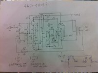
I would measure the voltage across that 10ohm 5watt resistor. If it says for example, .500v, you are pulling 50ma. I'm not sure what good it will do, though. That only tells you what they are both pulling combined.
You could add a 10ohm at the plate of each section, and then you could tell what each section is pulling. But again, not much use unless you have a way to make adjustments.
You could add a 10ohm at the plate of each section, and then you could tell what each section is pulling. But again, not much use unless you have a way to make adjustments.
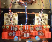
The problem is that I cannot seem to locate the cathode resistor to meter across. There are two 1 ohm resistors connecting to the top of each plate but I don't think that is the proper area to gauge the bias. Metering both of those gets me the balance between them.
I think the cathode resistor may be on the underside of the board. Does this seem right? Why would they try to hide that?
I think the cathode resistor may be on the underside of the board. Does this seem right? Why would they try to hide that?
Oh, the 1 ohms on the plates aren't on the schematic.. But, yes, you can measure the current each section of the tube is pulling w/ that.
Here's a thread about it.
http://www.diyaudio.com/forums/parts/141400-measuring-current-using-1ohm-resistor-how.html
The 5 watt cathode resistors maybe large, so they put them on top to have physical space for them... Who knows....
Here's a thread about it.
http://www.diyaudio.com/forums/parts/141400-measuring-current-using-1ohm-resistor-how.html
The 5 watt cathode resistors maybe large, so they put them on top to have physical space for them... Who knows....
Interesting idea of using a resistor to measure the Amps running through it. So when I read across each plate resistor, I get about 0.025v. So being that it runs through a 1 ohm resistor, each plate is using 25ma? Combined at the cathode it would be 50ma? So if trust that there is a 10ohm resistor down there, 50ma would make for .5v bias before that resistor? Is this the correct way of doing this?
Interesting idea of using a resistor to measure the Amps running through it. So when I read across each plate resistor, I get about 0.025v. So being that it runs through a 1 ohm resistor, each plate is using 25ma? Combined at the cathode it would be 50ma? So if trust that there is a 10ohm resistor down there, 50ma would make for .5v bias before that resistor? Is this the correct way of doing this?
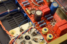
You already have the 10R resistors on each of the plates (highlighted in pink circles). So you could take voltage measurements across each of them. But please be extra careful, and make sure your DVM can handle the HV, use banana clips/clip leads on the resistors, do not attempt to hold the test leads with your hands while taking the measurements, one little slip, you can kill yourself and/or damage the tubes.
After taking the measurements, you can then adjust the 33K pot on each channel to balance the bias voltages to each half of the tube, unless the two halves are very mis-matched, you should not have to turn the dial much at all to get the bias voltages in line. If it still red-plates after the adjustment, something else is wrong...
Good luck and please be very careful when you do this!
An externally hosted image should be here but it was not working when we last tested it.
Jaz
Last edited:
Those resistors you circled are 1ohm resistors right? I had some confusion about them being they are not on the schematic. The colors are brown, black, gold and gold. The first gold being a 0.1 multiplier making it a 1 ohm resistor. If I wanted a bias voltage of 0.5v, I would want to adjust the trim to produce 0.025v across each plate resistor correct?
Those resistors you circled are 1ohm resistors right? I had some confusion about them being they are not on the schematic. The colors are brown, black, gold and gold. The first gold being a 0.1 multiplier making it a 1 ohm resistor. If I wanted a bias voltage of 0.5v, I would want to adjust the trim to produce 0.025v across each plate resistor correct?
I think they are 10R, since there are 5 band not 4, either way, so set the DVM to read 25 or 2.5 on either the 100mV or 10mV scale, then 0.050*10=0.5V is the bias current for both halves.
Jaz
Well, looks like it worked! All the numbers now align up and all things seem to check properly! I removed the troubled FU-29 tube and swamped it with a GU-29 tube and nothing appears to be red-plating. Sounds crisp and stable. I haven't reached my 40 minuet mark yet in run time, but looks like it was just a faulty FU29 tube initially. Thanks guys for helping me out with this one!
Just wondering if some one could post a photo where I could take the reading to bias this new audioromy amp.
I have found this:
Audioromy FU29 828 - AudioKarma.org Home Audio Stereo Discussion Forums
ive seen this. i bought this audioromy from this owner.
i bought another one last week and its newer. it has a different board, the same as the photos on the first post.
Attached Thumbnails


Hi,
I'm writing from Fance.I bought one of this amp and I tried to measure voltage for the biais but I touch one pot. After that one valve get red and if I measure the value of each pot one seem to be out of order (not the same resistance like the others).
Is someone could help me and tell me what I can do with my amp ?
Thanks for your answers
- Status
- This old topic is closed. If you want to reopen this topic, contact a moderator using the "Report Post" button.
- Home
- Amplifiers
- Tubes / Valves
- fu-29 Audioromy