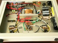
I got my hands on cute little Almarro A205A MkII amp and the first thing I did when I received it was to unbolt bottom cover and inspect the circuitry. It is EL84 SEP with feedback. Its point to point construction and ample space will lend itself well to tweaks and modifications that would make this amplifier more flexible in terms of configuration.
I would like to make the amp Pentode - Triode mode switchable. Other things to try would be adjustable NFB. The EL84 socket pins 3 and 6 are not connected together, tying them together or installing "Hazen mod" cap would enable the use of SV83 pentodes.
Has anybody tried any modifications other than obvious coupling cap changes and what were the results?
Link on "Hazen mod": http://www.diyaudio.com/forums/tubes-valves/153779-anyone-try-hazen-mod-g3-supressor-grid.html
6 moons review: 6moons audio reviews: Almarro A205A MkII
Attachments
To run sv83 you will need to reduce the value of the cathode resistor, and pay attention to the g2 ratings. The ruggedized version (6p15p-eb) will stand higher g2 voltage, but you are still limited to 1.4w g2 dissipation. I haven't tried the hazen mod, but I run them with g3 tied to the cathode. They are good sounding tubes, in triode mode, I think they may sound better than el84's, which is a very good sounding tube. I run sv83 in a rh-partial feedback style amp that has been set up for sv83 (lower value cathode r than el84, and regulated g2 voltage of 195).
Hi Jim,
Thank your for your suggestions. I will measure the voltages on the amp and calculate the proper value of Rk for SV83. I think SV83 is close enough to EL84 to be run without modification of Rk values in Almarro. The idea is to make tubes interchangeable without having to swap internal components.
Thank your for your suggestions. I will measure the voltages on the amp and calculate the proper value of Rk for SV83. I think SV83 is close enough to EL84 to be run without modification of Rk values in Almarro. The idea is to make tubes interchangeable without having to swap internal components.
OK, you basically have three different choices for three very different kind of sounds: as it is (pentode with GNFB) , triode with NO negative feedback (just break the feedback loop somewhere) and what is called Schade feedback. It is a question of personal taste. I think you should try all of them. In my opinion the one you have now is the worst sounding of the three. For the 'Schade mod' you need to change the input tube and its values. Just a few resistors, nothing complicated. To find out the values for those resistor check the RH84 schematic out. Easy enough to find. That one uses a 12AT7, you can also use the ECC88 but it requires other values and the pinout of the tube is different. More work.
The "Hazen mod" is a very minor mod compared to the ones I just listed you.
The "Hazen mod" is a very minor mod compared to the ones I just listed you.
Thank you for suggestions. Again, the goal is to leave the amp basic structure intact, allowing swaps and changes with one or two switches - no major surgery.
I put a 0.1uf cap between G3 and k and plugged 6p15p-ev tubes just to try - it sounded good at lower levels, distortion on higher levels, not good. I suppose I will stick to EL84 pentode/triode configuration for the sake of simplicity of the mod.
Triode/Pentode switch looks very easy to implement.
I put a 0.1uf cap between G3 and k and plugged 6p15p-ev tubes just to try - it sounded good at lower levels, distortion on higher levels, not good. I suppose I will stick to EL84 pentode/triode configuration for the sake of simplicity of the mod.
Triode/Pentode switch looks very easy to implement.
Last edited:
An obvious improvement to pentode mode is employing regulated g2 B+. It looks like there is plenty of room for a Maida regulator.
If you are going to use the 6П15П in triode mode, follow the DECWARE SE84 example and tie g2 to the plate via a 1KOhm resistor. Protect that fragile screen against excessive dissipation.
If you are going to use the 6П15П in triode mode, follow the DECWARE SE84 example and tie g2 to the plate via a 1KOhm resistor. Protect that fragile screen against excessive dissipation.
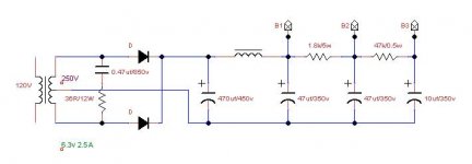
Here's the rendition of Almarro power supply. The HV secondary could be configured to 220v CT or 250v CT by placing two fuses in different slots, currently 250v is selected. Heaters are AC fed from 6.3v @2.5A secondary which is probably not enough - PS transformer gets real hot during operation.
B1 - EL84, B2 - EL84 G2, B3 - 12AX7
One way to improve power supply could be bypassing second and last electrolytic with small value quality film caps. Large film cap instead of lytic in the last position would be ideal, but fitting may be an issue.
B1 - EL84, B2 - EL84 G2, B3 - 12AX7
One way to improve power supply could be bypassing second and last electrolytic with small value quality film caps. Large film cap instead of lytic in the last position would be ideal, but fitting may be an issue.
Attachments
An obvious improvement to pentode mode is employing regulated g2 B+. It looks like there is plenty of room for a Maida regulator.
If you are going to use the 6П15П in triode mode, follow the DECWARE SE84 example and tie g2 to the plate via a 1KOhm resistor. Protect that fragile screen against excessive dissipation.
6p15p may require changing operating points that are suitable for this tube only, which is not what I'm after. It is an interesting suggestion, however.
I am a big fan of regulation, - B+, heaters, bias, CCS, etc. Not on this amp...
I bypassed B1 and B3 electrolytics with 0.47uf auricaps i had in my bin - audible improvement.
You have heater current to spare. ") If you want the power trafo to run cooler, use a 47 μF. 'lytic in the 1st filter position and the 470 μF. 'lytic in the reservoir (2nd) position. B+ rise will slow down too.
If you want the power trafo to run cooler, use a 47 μF. 'lytic in the 1st filter position and the 470 μF. 'lytic in the reservoir (2nd) position. B+ rise will slow down too.
What is the # of the OEM SS diodes? UF4007s cost approx. 15 cents each and produce much less switching noise than other PN junction diodes do.
If you want the power trafo to run cooler, use a 47 μF. 'lytic in the 1st filter position and the 470 μF. 'lytic in the reservoir (2nd) position. B+ rise will slow down too.What is the # of the OEM SS diodes? UF4007s cost approx. 15 cents each and produce much less switching noise than other PN junction diodes do.
You have heater current to spare.
What is the # of the OEM SS diodes? UF4007s cost approx. 15 cents each and produce much less switching noise than other PN junction diodes do.
I couldn't see the numbers on diodes - too small and soldered blank side up. Could be of MUR series...
Attaching schematics with component values.
I suppose there are variations in power supply modules (at least from the pictures that I have seen), also the schematics are inaccurate in terms of NFB wiring and headphone jack connection. The signal ground to chassis is connected at 12AX7 socket via 5 ohm 5W resistor. There is also a thermistor near the power switch (at least it looks like one, black disc of appropriate size), probably to save fuses from blowing on the initial monster 470uf cap charge.
Attachments
Last edited:
Just to follow up...I finally got bored (annoyed) with Almarro and "swapped" it for a pair of Wright WPA 3.5 monos - sonic bliss.
I acquired Almarro A205a following reviews, some of them high on superlatives, 6moons, stereophile, etc. Graphomaniac poetry aside, Almarro is quite mediocre in terms of SQ, especially in pentode mode. Nothing special in circuitry, power supply or parts quality - everything is plain vanilla, - silicon diode rectification, AC filaments, CLCRC B+, usual cathode bias, cheap electrolytics everywhere...Meh.
I acquired Almarro A205a following reviews, some of them high on superlatives, 6moons, stereophile, etc. Graphomaniac poetry aside, Almarro is quite mediocre in terms of SQ, especially in pentode mode. Nothing special in circuitry, power supply or parts quality - everything is plain vanilla, - silicon diode rectification, AC filaments, CLCRC B+, usual cathode bias, cheap electrolytics everywhere...Meh.
SEP with global feedback: meh.
GNF is to be avoided.
Hi folks, it looks like this thread is fairly old, but I thought I'd post to see if anyone could help me. I picked up a used Almarro a205a a few weeks ago. Today, when I was changing capacitors, I noticed that one of the resistors had been snipped out of the circuit. I'm not an electrical engineer, and although I've been reading Morgan Jones' "Valve Amplifiers" book, I'm only on page 79. I'm assuming that this modification broke the negative feedback loop? (The amp plays.) But I don't know for sure.
I've already closed up the amp (plus I don't have a decent camera at home today--left it at work), but if you'd allow me to attach a very-bad visual aid, I've drawn a red line pointing towards the resistor that has been removed (it's on the right side of the photo, underneath the lead from the V-Cap.) If you are familiar w/ the amp, it's one of the two resistors that has had the leads bent through a couple of 90-degree elbows.)
1.) Should I try to get my hands on a circuit diagram and solder this resistor back in?
2.) If so, can anyone give me an idea which resistor this is, or what I should look for on the circuit diagram in order to find out the value? From looking at fuzzy images online, it doesn't seem to have the same value as the symmetrically-placed resistor on the other side of the socket.
Thanks, folks. --Mary
An externally hosted image should be here but it was not working when we last tested it.
- Status
- This old topic is closed. If you want to reopen this topic, contact a moderator using the "Report Post" button.
- Home
- Amplifiers
- Tubes / Valves
- Almarro A205A as experimentation platform