Jackinnj,
Do you have the ability to run a test with an external power supply? Ronald has updated his blog with further info regarding the PSU. (See Chapter 23) http://dos4ever.com/uTracerlog/tubetester2.html#heater
It will be a good exercise to run a set of plots with an internal vs external PSU and compare the curves.
I will try to do this over the weekend.
Last edited:
Jackinnj,
Do you have the ability to run a test with an external power supply? Ronald has updated his blog with further info regarding the PSU.
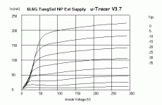
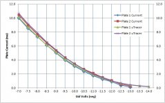
I ran some tests with external supply and they are beautiful.
i think that the PWM output could be configured for "buck/boost" converter, but the microchip is a bit slow for error correction.
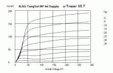
I did that test with a new production 6L6G TungSol, using both the internal heater supply and an external one.
In both cases the the same tube was used and the measurements were taken after 10 minutes of heating time to ensure emissivity was stable.
You can clearly see from the charts that although the "shape" of the traces remains similar, there is a "scaling" factor. In other words, less emission, less anode current.
Attachments
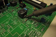
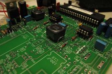
I really fail to see why the inductors are a problem - simply wipe a tiny amount of flux (from a flux pen) on the pads. Whilst holding an inductor in place, using 22SWG solder, sweat/capillary feed a small amount of solder under one pad. After ensuring your inductor is nice and square, repeat for the other pad. Takes about a minute to do one inductor. No messing with bits of looped wire or whatever. No heat damage to the pads, inductor, or anything else. If you want to make it even easier, just tin one pad, hold the inductor in place with a fingertip and re-flow the pad so the inductor drops into place. Let the pad set, then do the other one at your leisure (using the capillary method above).
Using thin solder and a decent iron its trivial to get right.
Using thin solder and a decent iron its trivial to get right.
Last edited:
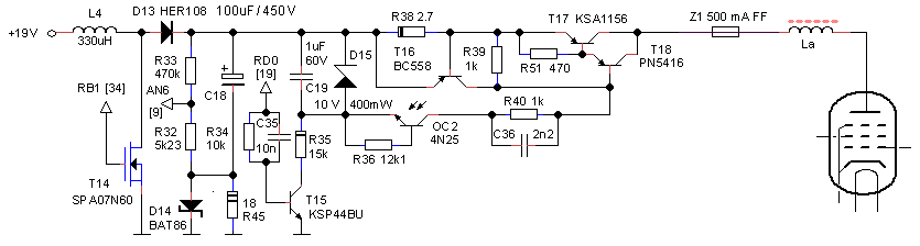
One of the issues for dealing with higher voltages/currents regards the switches. Ron uses an optocoupler and a "floating battery" concept to drive the switch. There are 2 high voltage P-channel MOSFETs which can be switched by a high-voltage N-channel MOSFET a la;
I've shown the Fairchild Device, there's also an STMicro STD3PK50Z for about the same price.
An externally hosted image should be here but it was not working when we last tested it.
I've shown the Fairchild Device, there's also an STMicro STD3PK50Z for about the same price.
Grid Bias Supply
The two BC556A transistors (T6/T7) comprising the current mirror in the bias supply are quite vulnerable to short circuits even when programmed for zero volts out. I quite successfully exploded mine.
I decided to replace them with Fairchild MPSW56 which are more rugged, have a BVceo of -80V compared to the -65V of the '556 noting a measured value collector to emitter of -74V.. IMPORTANT:They are pinned out in the exact reverse order of the BC556 so install them with the flat facing away from the flat on the silk screen. Beta is high enough that they work just fine.. (I did not even need to recalibrate when I checked the calibration.)
The MPSW56 will support an amp of collector current and dissipate a watt, this will hopefully be enough to survive a momentary short.
Currently the bias supply is protected by a 470 ohm resistor in series, but because I sometimes use a floating supply to buck the bias supply (offsetting by +2 to +10V**) for measuring some tubes with both negative and positive bias I plan to replace the resistor with a 100mA fast blow fuse to reduce errors in Vg when the grid starts to draw grid current..
** I use an old Power Designs 0 - 20V precision reference supply, output voltages can be set in increments of 10/20mV on the 10/20V ranges with an ovenized master voltage reference. It is sufficiently accurate I'd say.
uTgui: The alternate gui
I have been using this off and on in an attempt to generate pentode models of devices like the 6Z52P and 6Z9P without success, it seems to work fine with high transconductance triodes.
Something to note is this program has an odd quirk with the comm ports, it expects to see a minimum of two valid ports, and if they are present you may select either one, if however only one is present errors occur and you cannot connect to the uTracer.. The solution is simple, either a dual port RS-232 USB adapter or two adapters. Note that this subterfuge is not necessary with the standard gui.
I like the alternate gui a lot despite the quirks and hope that Nick Barton will eventually have time to refine it. (He's a bit busy right now)
I did many traces in a2 with very good results. Here is 4P1L example:
http://www.bartola.co.uk/valves/2013/09/29/4p1l-model-improved/
Cheers
Ale
http://www.bartola.co.uk/valves/2013/09/29/4p1l-model-improved/
Cheers
Ale
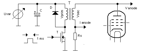
After studying the design of the uTracer v3, I have some concerns as to the accuracy of the measurements taken by it.
One concern involves the plate current sampling process; a charged capacitor (C18) is switched in to act as Vp while at the same time Ip is sampled. The moment Vp is switched in it will begin to droop. Is 1ms sample time long enough for every circuit node to settle? Does the SMPS try to maintain the voltage while the current is being sampled?
One other concern is the series inductor La. What effect is it having on this switched measurement process? Also, Vp is being sampled far from the tube anode.
I had a look also at the uTracer v4.0, and imho, using coupling transformers is a step in the wrong direction.
Maybe some compensation is being applied and my concerns are moot. Has anyone compared the uTracer results to a carefully-obtained set of DC sweep results?
Last edited:
Here is a indepth review with some test data using a bogey tube that might be of interest. I don't own an uTracer yet, but it is difficult for me to fathom that Dr. Dekker would bother releasing a design if it could not even perform the most basic function. Also could you please elaborate on "using coupling transformers is a step in the wrong direction..."?
Last edited:
Indeed assuming we are both looking at the same thing, those Bogey tube curves do not match well with the uTracer results.
Regarding the proposed v4.0 re-design using pulse transformers, the Vp will be switched through a step-up transformer which imho introduces more problems than it solves. There will now be challenges including calibration, inductive kickback, ringing etc.
Dekker is trying to keep the circuit small and cheap, which of course is a good thing. But there is a benefit of returns that should be kept in mind, and in this case I believe he is perhaps unwilling to sacrifice a bit of size/cost for accuracy and performance. I'd gladly pay more and put up with a bit bigger unit if certain design aspects weren't compromised.
With a few tweaks to his current v3 design, he could easily accomplish a higher Vp and positive grid voltage measurements. Also, double or triple the reservoir caps.
There is no need to utilize pulse transformers to achieve what he wants for v4.
Well I don't think the design of uTracer v.4 has been finalized, but the concerns you have with the flyback effect no doubt has crossed the good doctor's mind, besides I am pretty sure this (among many others) is an engineering and programming challenge that he would like to tackle... if it was easy, then anyone can do it, where is the fun in that?
I have looked at both the swept results and static, the uTracer v3.0 mA/Gm results are almost the same as calibrated tubes tested using multiple supplies, oscillator and high resolution meters. An example of a 6SN7 at 250V swept from -14 to -7V on the grid is provided, the resolution being quite fine where one can resolve small differences in almost identical plate curves. Other tubes such as 6L6 tested on an Amplitrex and AVO testers give results within 1% of the uTracer V3.0. The only caveat, is these results are obtained with an external power supply for the heater. The internal heater yields between 3-8% lower results, the higher the heater current, usually the lower the value. There are some small plate/screen volt deviations from there set point resulting from the scheme used, but these are very small and can be compensated for.
The blog on the uTracer v4.0 is interesting and discusses some of your points. As mentioned, I think it is more the challenge of the design and to see if some of the hurdles of using a step-up transformer can be compensated for.
The blog on the uTracer v4.0 is interesting and discusses some of your points. As mentioned, I think it is more the challenge of the design and to see if some of the hurdles of using a step-up transformer can be compensated for.
Attachments
Indeed assuming we are both looking at the same thing, those Bogey tube curves do not match well with the uTracer results.
<snip>
The reason the uTracer results don't match a bogey tube curve is because such a tube does not exist. The curve is the average of many, perhaps even hundreds or thousands of tubes. Testing multiple tubes on the uTracer shows this very clearly - and the results are quite repeatable over time and instance.
I have had a number of problems with the filament supply and will shortly be building a supply to power the filaments of the DHTs I want to test. I will also use this supply to correlate measurements between the internal and external filament supplies.
I have found it to match static measurements quite well when the heater voltage issue is properly addressed.
It provided me with enough insight to design my first phono stage with a pentode front end. Characterizing several different types with the uTracer gave me the confidence to proceed. (I'm listening to that phono stage right now.)
The reason the uTracer results don't match a bogey tube curve is because such a tube does not exist. The curve is the average of many, perhaps even hundreds or thousands of tubes. Testing multiple tubes on the uTracer shows this very clearly - and the results are quite repeatable over time and instance.
Yep: http://www.diyaudio.com/forums/tubes-valves/243950-vacuum-tube-spice-models-16.html#post3750924
The reason the uTracer results don't match a bogey tube curve is because such a tube does not exist.
I found that on some tubes the curves I derived on the u-Tracer and the fitted out Tektronix 576 were quite comparable to the datasheets -- compared to the Tektronix 576, however the u-Tracer is quite current limited.
- Home
- Design & Build
- Equipment & Tools
- uTracer...