Ive been working on this preamp for over a month now with no luck. Pretty much every part of it has been rebuilt or replaced and I'm now out of ideas. The high frequencies begin to roll off at about 1k and are about 25dB down at 20k! I'm sure all of this is happening in the first gain stage as the same frequency curve is present at its cathode as at the output of the entire preamp.
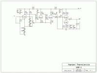
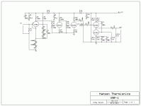
Here's the basic design: EF86 DC coupled to 1/2 ECC83 DC coupled to 1/2 ECC83 AC coupled to ECC82 White cathode follower via a 1M pot.
It started off all AC coupled, but as I said, I've rebuilt the whole thing! Also I've rebuilt the EF86 stage to use a couple of diodes on the cathode and some zeners on the screen grid. No change.
If I had any hair I'd be pulling it out! Please help!
I'm using a signal generator (a log sine sweep) in cubase and i can check whats going on in different parts of the preamp with my audio probe. I've measured an almost ruler flat response at the output of the Lundahl 1538 input transformer. The response is flat at the grid of the EF86, I even removed the grid stopper resistor to make sure!
I've just downloaded expressSCH so I'll have a go at drawing a schematic when I get home tonight.
I've just downloaded expressSCH so I'll have a go at drawing a schematic when I get home tonight.
Sounds like the upper halve of a RIAA correction.Something around the EF86 that's a leftover from an earlier build ?The high frequencies begin to roll off at about 1k and are about 25dB down at 20k! I'm sure all of this is happening in the first gain stage as the same frequency curve is present at its cathode as at the output of the entire preamp.
Mona
Sounds like the upper halve of a RIAA correction.Something around the EF86 that's a leftover from an earlier build ?
Mona
Not sure what that means, a quick google search tells me its an emphasis/de-emphasis EQ for vinyl. How would I have accidentally done that? It's a simple EF86 pentode gain stage with 100k anode load, 68k from B+ to screen with three 24V zeners going to the cathode (bypassed with 100n to reduce noise) and two 1N4007 diodes from cathode to ground.
From memory the B+ is 250v, screen is at 73V cathode is at 1.2V and I cant remember what voltage the anode is at. The output is taken directly from the anode and a 1M/470k voltage divider feeds the next grid.
For the time being I have removed the input transformer and there is just a 1M grid leak resistor.
This will be easier when I have the schematic drawn!
Well perhaps not in your case,but sometimes an old preamp is used for other purposes,throwing out what is supposed not nessesairy.
Better wait for a schematic.But I have to say,the hole idea of a mic pre with a noisy EF86 (low frequency region,current repartition a/g2) and a lot of junk around it,is not the best way.
Mona
Better wait for a schematic.But I have to say,the hole idea of a mic pre with a noisy EF86 (low frequency region,current repartition a/g2) and a lot of junk around it,is not the best way.
Mona
If that really is the circuit you are using then poor behaviour is to be expected. Many of the resistor values are completely wrong. Miller effect will give you serious treble rolloff. That is not a mike preamp; at best it is a peculiar guitar FX box. Removing caps and replacing them with something which is far far worse is not a good way to improve a circuit.
Don't blindly imbibe the 'capacitor phobia' exhibited by some on here; instead, learn about valve circuit design.
Don't blindly imbibe the 'capacitor phobia' exhibited by some on here; instead, learn about valve circuit design.
To go along with DF96's observation: I may have pressed some buttons wrong but it looks like the overall gain of each 12AX7 stage is ~.45? That seems like an end result that is opposite of what the 12AX7 is intended for signal amplification. Are you sure what you have drawn is correct?
There's nothing in the circuit to give the reported frequency problem. There's a lot of wasted gain, for the purpose presumably of harmonic enhancement and sharpish roll-off.
Something's missing from the diagram, or the EF86 is faulty, assuming you measured the frequency response at its input.
Something's missing from the diagram, or the EF86 is faulty, assuming you measured the frequency response at its input.
My intention is to use a dual gang 100k pot to dial in some large bypass caps on the ECC83s cathodes as a gain control. So in the schematic the gain is the lowest it can be. I have not included the bypass caps because they are currently missing from my build.
The DC coupling is to avoid blocking distortion on bass heavy sounds and provide a flat response right down to DC. The preamp is intended to distort or be clean when it is desired.
The design as it is now is basically taken from Merlin Blencowes example circuits in his preamp design book (though it's a guitar/bass design book it does also give hifi examples for completeness). I didn't expect any resistor values to be completely wrong. Which ones were you talking about?
Also the EF86 is not faulty, I swapped it out for a known working one and the response was the same. :-(
No joy, I've just AC coupled the EF86 to the ECC83 in case it was something to do with that. No change. Btw the 1M resistors are not grid stoppers, just part of a voltage divider. And the treble loss is in the EF86 stage, is perfectly flat in the rest of the preamp.
I also tied the screen diodes to ground instead of the cathode, no change.
Could it be something in the power supply maybe? I have to go out now but when I get back I'll complete the schematic.
If it makes more sense to you guys, I'm trying to make a sort of Culture Vulture-esque mic preamp for plenty of colour and grit with the gain turned up, but when the gain is backed off, clean enough for rock'n'roll. Hi-Fi is not my ultimate goal.
I'll report back in a few hours. Cheers guys.
The gain control is in the wrong place for this; you need to move it earlier in the circuit. As it is you will simply be able to adjust how much output you get, with "colour and grit" determined solely by input signal level.Andyroid said:If it makes more sense to you guys, I'm trying to make a sort of Culture Vulture-esque mic preamp for plenty of colour and grit with the gain turned up, but when the gain is backed off, clean enough for rock'n'roll. Hi-Fi is not my ultimate goal.
There is nothing in the circuit which would cause serious HF rolloff in the first stage. Therefore either this is not what you have built, or you are not measuring what you think you are measuring.
If you see the roll off on the cathode and the tube is ok it is likely that the roll off is also present on the g1. If the signal on the socket is pin is ok, could it be a bad contact in the socket? Try to lift the tube a bit in the socket an measure directly on the tube pins for comparison. Also please let us know the DC voltages on all pins so the experts can judge the op.
And can please explain what your "audio probe" is?
And can please explain what your "audio probe" is?
- Status
- This old topic is closed. If you want to reopen this topic, contact a moderator using the "Report Post" button.
- Home
- Amplifiers
- Tubes / Valves
- Mic preamp - strange high frequency roll off problem

