Hi!
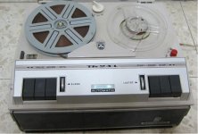
During the repair of a 50 year old Grundig open reel tape machine (TK23L), I traced the fault to the output transformer (no anode voltage on the output valve, excessive current on g2 and trough it's resistor with HT on normal levels).
The output stage is a ECL86 triode/pentode and the output transformer is directly and permanently connected to the built-in 4 Ohm speaker.
After dismantling the transformer and unwinding it's primary, the wire was open in six different locations. The interruptions originated in black spots spread throughout the windings (different layers, different places within the transformer, that is, not aligned with each other).
Transformers being generally robust and well built (particularly these old ones) what could have caused the destruction? Manufacturing defects is obviously ruled-out as well as corrosion (the impregnation rosin was still sticky inside the windings, despite the age).
I already have a replacement transformer but am not confident about turning the machine on before I understand what could possibly have happened for I don't want to risk blowing the replacement.
Any help from anyone regarding the possible causes for the destruction of the original transformer after 50 years of faithful service?
Thank you for your help,
Regards,
Renato
ps: the end of the transformer came slowly (lasted for weeks) with intermittent sounds difficult to describe, something like the sound of tearing a paper sheet very slowly or a deep 'grinding' sound.
Attachments
Dampness causing electrolytic corrosion where the enamel wire coating was cracked due to age? In use the primary is sitting a few hundred volts above ground and the transformer frame is probably grounded. It doesn't take much moisture to get a little current flowing. A big current will take a short time to corrode metal. A little current might take 50 years.
Hi Renato
Do not install the new transformer before you troubleshoot the output stage.
The usual suspect for failed primary of output transformer is the coupling capacitor between the anode of the driver triode and the screen of the output pentode. If this cap is leaky, DC from the triode anode makes the pentode screen very positive, increasing the anode current and burning the thin secondary coil (the pentode may survive)
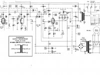
As your schematic has the EL95 (pentode) as the output tube and not the ECL86, I attach the output stage with the ECL86.
I would then first check the capacitors C9 and C17 for leakage.
George
Do not install the new transformer before you troubleshoot the output stage.
The usual suspect for failed primary of output transformer is the coupling capacitor between the anode of the driver triode and the screen of the output pentode. If this cap is leaky, DC from the triode anode makes the pentode screen very positive, increasing the anode current and burning the thin secondary coil (the pentode may survive)
As your schematic has the EL95 (pentode) as the output tube and not the ECL86, I attach the output stage with the ECL86.
I would then first check the capacitors C9 and C17 for leakage.
George
Attachments
gpapag,
Thank you for your fast answer! Before disclosing what was wrong, I measured all the voltages in every tube: all was as expected except for the anode voltage on the ECC86 pentode (that lead me to the faulty transformer). The grid voltage on the same pentode was low as expected (so, the transformer didn't expire from this, I think). Nevertheless I tested C9 & C17 and they are fine. I also measured the grid resistor (10K) and the grid leak resistor (2,2M) and the values matched (by the way, thank you for the schematics: I seem to have posted the wrong one - oops!).
Ruling out the chance of excessive voltage on the transformer, I decided to connect the new one and got a huge hum on the speaker. I then replaced C23 (even though the capacitance tested ok; I don´t have a ESR meter) and started getting results: some sound from the tape but dim and humming. Then I replaced C22 and the humming disappeared at normal volume playback. However, when turning the volume up, a very high pitch sound (ear piercing, almost ultrasonic) starts and the volume pot screeches (may be dirt, though, or too much current passing through and damaging the carbon track) even with the tape on 'pause'.
The voltages on every valve check with the values on the schematics (only about 20% lower) which I don´t think is significant.
So now I'm stuck. Any ideas about where to start? A brutish way would be to start replacing the capacitors one-by-one but I would like to take a more intelligent approach!
And still, the origin of the transformer destruction remains undisclosed... Six rupture points is massive, I think, for a well behaved home amplifier!
Opinions welcome!
Thank you all,
Renato
ps: I checked the speaker switch and it is working; I also checked the oscillator coil and there was no short (and measured about 1,2 Ohm on the primary).
ps:
I also checked the oscillator coil and there was no short (and measured about 1,2 Ohm on the primary).
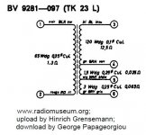
Correct. See attachment
However, when turning the volume up, a very high pitch sound (ear piercing, almost ultrasonic) starts
Now we are talking! (there is work for you
") ).
).HF Oscillation can burn the output x-former primary coil at many points which are many turns apart, due to charging of inter-winding capacitance/coil inductance hf tank circuit.
Before looking any deeper, due to the many mechanical contact points that are within feedback loops (common design issue with equipment of that era), I would apply contact cleaner (with no oil) on all the switches and exercise them many times (electrical power removed of course).
I would also remove all the tubes from the sockets, apply this contact cleaner and reinstall them (handle the tubes gently!)
Then I would apply contact cleaner (oily this time) on all the potentiometers and exercise them.
After all this, if the hf oscillation is still there, I would suggest to start the rewarding part of the job.
Do you have an oscilloscope (and a sine wave generator)?
If not an oscilloscope, is there a decent AC voltmeter available?
Do you have the full schematic diagram? (I can post it )
Reply and we can proceed if needed.
George
Attachments
Dear George,
I'm at a loss. After cleaning all the contacts, instead of a high frequency sound, I got a low frequency one. After replacing the pentode's cathode capacitor (C20) the HF noise was back. After replacing the triode's cathode capacitor (C8) the LF noise came back...nothing makes sense here.
Regarding the signal generator and the oscilloscope I'm afraid I don't have one (and even if I did, I wouldn't know how to use it; using the multimeter is as far as a pharmacist goes!). I'm begining to think this is way above my skills but the problem is that if I don´t do it myself, nobody around here is going to do it for me.
As for the decent voltmeter I have a decent one I think I can trust. I would also appreciate if you could post the schematics: tho one I have is a poor scan and sometimes difficult to read (and I also don't have the PCB layout which means I have to follow the tracks to find a specific component...).
Thank you again for your help and patience,
Renato
Hi-Q: I can't find any of these inside. The signal ones are ERO foil IIs the WIMAs are round yellows and the electrolytic, mostly Siemens.
I'm at a loss.
Renato
Save these feelings for more serious troubles (e.g. women
). Not for electronics.After you cleaned all the switches with the spray did you worked all the switches many times (without electric power connected)? It is important to do this.
Do all these noises occur when you play back a tape only or they occur also when you select the other inputs (microphone, radio, gramophone). Check each one.
Do you have a microphone that you can connect to the mic input? Does it work? What do you hear from the speaker?
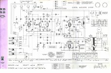
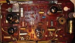
Please, if possible, take a picture of the pcb from the components side and post it. I am interested to see the type of the capacitors.
George
Attachments
Dear George,
Sorry for the long absence but I've had other urgent matters...
Thank you for the excellent schematics: a HUGE improvement on the ones I had where I had to half-guess the numbers!
I post one picture so that you can see what kind of capacitors are in the circuit. The player has certainly been serviced before: It's been in my family from the beginning and there are memories of that, even though I can´t say what was repaired; most surely the EF86 pentode cathode decoupling capacitor (C20), R36, R57 and maybe the pentode's cathode decoupling capacitor too(C8).
Regarding the contacts, I've cleaned all of them with Kontakt Chemie cleaner number 60 to no avail.
I've also measured the voltages on all valves and found that the ECC81 has some strangely high grid values which I can't explain and which are not present in the schematics (but, after all, I can't really understand the function of this valve because it seems outside the signal path - or maybe I'm missing out something, which is probable). I can't also understand the way the oscillator coil works for it seems like a transformer injecting the signal from the reading head directly to the output stage... I've tried to find some explanation on the internet but the subject is either too obvious or too out of fashion for someone to have it explained.
The voltage readings (to earth) are as follows:
HT 232V
EF86
anode(pin6) 31V
g1(pin9) 1,1V
g2(pin6) 31V
EF83
anode(pin6) 46V
cathode(pin3) 1,1V
g1(pin9) 0,02V
g2(pin1) 21V
ECC81
anode(pin1) 227V
cathode(pin3)47V
grid(pin2) 20V (???)
anode(pin6) 221V
cathode(pin8) 19V
grid(pin7) 0,3V
ECL86
anode triode(pin9) 141V
cathode triode(pin2) 0,9V
grid triode(pin1) 0,12V
anode pentode(pin6) 208V
cathode pentode(pin7) 4,6V
g1(pin8) 0,2V
g2(pin3) 203V
Another strange finding is the temperature of the end valve ECL86: too high in my modest opinion (can hardly be touched after a one or two minutes of operation; thought about measuring the current flowing through both cathodes but haven't done it yet for I'm not sure my meter will be sensitive enough for that).
Don´t know what to do next... every effort has failed so far.
Thank you so much,
Renato
ps: just noticed that when the mains plug is inverted the high frequency pitch is replaced by a low frequency one; that might explain the previous reports I posted because I wasn't paying attention to the position of the plug (we have reversible ones in here).
pps: the replacement output transformer is correctly wired according to the colour coding.
Attachments
- Status
- This old topic is closed. If you want to reopen this topic, contact a moderator using the "Report Post" button.
- Home
- Amplifiers
- Tubes / Valves
- Output transformer: reasons for destruction?