Hi,
I'm new to diy audio and have no experience in modifying amps. Few months ago I bought a Bewitch KT88 on ebay and so far I like it a lot, one of the reasons I bought the Bewitch was the positive review on the Lampizator website (Bewitch).
He also made a recommendation on some mods. I'm planning to follow his mods, but recently I heard from some people that the Lampizator mods might not be as good as he claims.
Can somebody give me some information about this mod?
http://lampizator.eu/AMPLIFIERS/CHINA/bewitch 6550/IMG_5577.jpg
My 2 cents about the modifications:
- Adding those Cap's should be simple
- Still the worst thing is the fixed bias using a Electrolyte Cap. The issue here is the absorption voltage given from the Electrolyte Cap. The get ride requires a negative voltage. I did this on my SLM-100 and the sound was more clear, no more echo's...
- An other simple tuning is to peel the Electrolyte Cap's as mentioned in old thread. This improved on my SLM-100 Cary a lot (some weeks ago I replaced the old cap's with new once, first without the peeling and the sound was very closed and after the peeling I went back again!) , but I do not know how this will improve on your amplifier.
see old thread from 2002:
http://www.diyaudio.com/forums/parts/6031-removing-plastic-covers-capacitors.html
Removing the plastic cover from a cap might alter the sound, but not for the better. The most likely outcome is no change. The next most likely outcome is microphony or a poorly damped mechanical resonance (which the plastic was suppressing by being mechanically lossy).
Bypassing the electrolytics might improve things a little, or make things worse (by introducing a resonance), or make no audible change at all. Removing the global negative feedback will raise gain, distortion and output impedance while reducing bandwidth. It will certainly change the sound.
Mr. Lampizator's audio ideas are best regarded as being somewhat eccentric.
Is there room to add a small transformer to get -90vdc for adjustable fixed bias? I just used a small 110 to 6vac iron connected backwards to the 6.3 filament output from the power transformer, diode and cap, resistive divider to a pot for each tube. if the pot fails, the voltage goes neg to turn off the tube. That should put an additional 40 volts across the output tubes, with 10ohm resistors to ground on their tails to monitor the bias current. Leave the GNFB, with the 180k there really is not a lot of it.
It would help to know the voltages for the bias points on the tubes.
It would help to know the voltages for the bias points on the tubes.
Please take a look at
http://frank.pocnet.net/sheets/164/k/KT88spec.pdf
The KT88 is a direct replacement for the 6550 except for an adjustment on the bias voltage and the heater current drawn!
Lovely valves. I have a pair working in my Fender Twin Reverb and they are so full of life compared with the original 6L6GC.
http://frank.pocnet.net/sheets/164/k/KT88spec.pdf
The KT88 is a direct replacement for the 6550 except for an adjustment on the bias voltage and the heater current drawn!
Lovely valves. I have a pair working in my Fender Twin Reverb and they are so full of life compared with the original 6L6GC.
Btw, the overall design looks somewhat weird to me. Where does phase inversion occur? Within the first tube? With it's tiny common cathode resistor? So, within the second one? But why, in this instance, the quasi symmetric approach of the first stage?
Anyway, I agree with DF96 - removing the negative feedback loop is probably the worst thing anyone can do to an existing design.
Best regards!
Anyway, I agree with DF96 - removing the negative feedback loop is probably the worst thing anyone can do to an existing design.
Best regards!
Last edited:
Yes, it looks like the first stage does a partial phase split which is then finished off by the second stage. Maybe the designer was a fan of circuits which look balanced, but actually are not? Feeding the NFB back into a partial phase splitter raises issues of common-mode distortion too, although the relatively low signal level might avoid too many problems.
Still, at least it doesn't have the apparently obligatory Chinese SRPP stage!
Still, at least it doesn't have the apparently obligatory Chinese SRPP stage!
Kay Pirinha and DF96,
You are both correct, the second stage is the phase splitter. The first stage top tube provides the bias to the top second stage, but Extremely low drive signal.
But the second stage needs a real current source (not a parallel of 10k of coupled cathode resistance).
Or else as a compromise, it needs properly adjusted Un-equal plate loads to match the gain of the two phases.
But I hate un-matched plate loads, they are just a compromise. You get 2nd harmonic matching only at one range of signal levels, either at low, medium, or large signal levels
. . . pick one signal level.
If not, the second stage will generate unnecessarily large 2nd harmonic drive to the outputs, with the global negative feedback the only thing that reduces that 2nd harmonic distortion.
With the un-matched plate loads to fix the 2nd harmonic D, I wonder and worry what it does to the,3rd HD, and to the 2nd and 3rd IMD.
With un-matched plate loads, there is the issue of the match going away as the tube ages, and also when you change tubes, you need to re-match.
Make the circuit relatively linear in the first place, and then add global (or local) negative feedback to lower the output impedance, and to do some slight correction for everything else.
Last edited:
 Just for some 3-way bookshelf speakers in my office.
BEWITCH 6550 - Any further thoughts?
I hope nobody minds me giving this oldish thread a bump...
We recently purchased a nice, preloved BEWITCH 6550 amp and are impressed with how it sounds.
The amp in its (reasonably) stock format has too much Gain for us however - which makes the stock (ALPS BLUE) volume pot almost unusable with our efficient speakers.
I have been thinking of changing the preamp tubes from 1 x 6N9P (6SL7 High Gain) and 1 x 6N8P (6SN7 Reduced Gain) to running two 6N8P instead - as proposed by the Lampizator author. With this in mind - and to achieve adequate Gain for the circuit, using 2 x 6N8P per channel - I understand that halving the values of resistors R2 / R3 / R4 / R5 will deliver this outcome; without causing other problems - and possibly providing better sonics, purely because the 6N8P is a better sounding tube than the 6N9P. Would the panel agree with this thinking and support this change?
As an aside, the previous owner has made a couple of upgrades already - seeking to extend frequency bandwidth: as follows: -
With the previous (thread below) discussion around the complexity of the NFB loop on this amp, I was thinking to leave the NFB well enough alone - although it is tempting to try resistor R14 100K at (say) 200K or more. Worth a try?
I am also wondering what Lampizator was looking to achieve, by bypassing C9 33uF/400V with a 68uF/600 MKP - AND removing R22 completely. Is this an attempt to make the Power Supply less noisy?
Finally, I have ready many times that the quality of the rectifier tube can have a big impact on sound quality. Our BEWITCH currently runs the original Chinese 5Z4P rectifier tubes - and gives no problems. But I do have a couple of nice 1940s Westinghouse Canada VU71/5U4G (NOS) tubes that I'm hoping might suit this amp - in substitution for the current 5Z4P tubes. Can anyone see any merit or problems with this substitution?
I'm keen to understand what the more experienced circuit designers make of the thoughts above, on this BEWITCH 6550 amp circuit.
Appreciated.
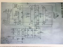
[I have attached what I understand to be the original BEWITCH circuit schematic - including the circuit changes that have already been completed...]
I hope nobody minds me giving this oldish thread a bump...
We recently purchased a nice, preloved BEWITCH 6550 amp and are impressed with how it sounds.
The amp in its (reasonably) stock format has too much Gain for us however - which makes the stock (ALPS BLUE) volume pot almost unusable with our efficient speakers.
I have been thinking of changing the preamp tubes from 1 x 6N9P (6SL7 High Gain) and 1 x 6N8P (6SN7 Reduced Gain) to running two 6N8P instead - as proposed by the Lampizator author. With this in mind - and to achieve adequate Gain for the circuit, using 2 x 6N8P per channel - I understand that halving the values of resistors R2 / R3 / R4 / R5 will deliver this outcome; without causing other problems - and possibly providing better sonics, purely because the 6N8P is a better sounding tube than the 6N9P. Would the panel agree with this thinking and support this change?
As an aside, the previous owner has made a couple of upgrades already - seeking to extend frequency bandwidth: as follows: -
- C3 and C4 have both been bypassed by an audiophile quality Polypropylene Cap 2.2uF/400V; and
- R1 has been bypassed by a audio quality Cap 100uF/25V
With the previous (thread below) discussion around the complexity of the NFB loop on this amp, I was thinking to leave the NFB well enough alone - although it is tempting to try resistor R14 100K at (say) 200K or more. Worth a try?
I am also wondering what Lampizator was looking to achieve, by bypassing C9 33uF/400V with a 68uF/600 MKP - AND removing R22 completely. Is this an attempt to make the Power Supply less noisy?
Finally, I have ready many times that the quality of the rectifier tube can have a big impact on sound quality. Our BEWITCH currently runs the original Chinese 5Z4P rectifier tubes - and gives no problems. But I do have a couple of nice 1940s Westinghouse Canada VU71/5U4G (NOS) tubes that I'm hoping might suit this amp - in substitution for the current 5Z4P tubes. Can anyone see any merit or problems with this substitution?
I'm keen to understand what the more experienced circuit designers make of the thoughts above, on this BEWITCH 6550 amp circuit.
Appreciated.
[I have attached what I understand to be the original BEWITCH circuit schematic - including the circuit changes that have already been completed...]
Attachments
Last edited:
As this mp uses NFB, using tubes with less amplifications will increase dist but
make very little volume change.
What you should do is to add a resistive divider at the input. The solution with
the viper direct coupled to the grid is not good, make the viper connect to
a series resistor , 220k and after that a resistor 100k to ground and the grid of the first tube.
This will reduce the input sensitivity with 2/3
The 100uF cap at the first tube ( LTP phase inverter !) should be removed as this
will prevent any phase inversion at this stage, forcing the NFB to partly compensate.
The 2.2uF caps paralleling the 0.47 caps should be removed, they will only
make the amp unstable and increase dist at low freq.
Removal of R22 will increase voltage to first tube, i would recommend to
put it back into service.
Bypassing electrolytes with film caps will do no harm.
Last edited:
Thank you...
@petertub
Many thanks for this thoughtful response.
It seems that it might be easier if I reduce the signal before the amp, for greater use of the volume pot.
So if I understand correctly, I should start by returning this amp circuit back to its original design and have another listen.
Thereafter, judicious installing of some very low value (.01uF) polypropylene caps - adequate voltage - to bypass electrolytic caps, in both Power Supply and Amp sections.
Finally, I might try some better quality resistors in R1 / R2 / R3 / R4 / R5 and have another listen...
Am I on the right track here?
Last edited:
Close. But skip the added caps and replacements of resistors, that won't add@petertub
Many thanks for this thoughtful response.
It seems that it might be easier if I reduce the signal before the amp, for greater use of the volume pot.
So if I understand correctly, I should start by returning this amp circuit back to its original design and have another listen.
Thereafter, judicious installing of some very low value (.01uF) polypropylene caps - adequate voltage - to bypass electrolytic caps, in both Power Supply and Amp sections.
Finally, I might try some better quality resistors in R1 / R2 / R3 / R4 / R5 and have another listen...
Am I on the right track here?
to the sound.
- Home
- Amplifiers
- Tubes / Valves
- Bewitch KT88