I found a schematic the other day for a regulated power supply,and I made some changes,replaced an EL34 used for the feedthrough with a 6550,and replaced the the high voltage silicon transistor with a 12AT7 tube used for part of the error correction amp. Wanted to know if posted schematic needs any other changes. I can post original if needed. Original schematic gives an output from 60 to 400VDC at 150mA.
Attachments
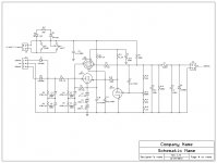
V1 should be negative biased. With R13 in mid pos the bias voltage will be about 1/2 B+ in this setup..Wanted to know if posted schematic needs any other changes.
You shoud'nt put the heaters on the same transfo winding.Check the max.permissable voltage between heater and cathode !
Mona
I'm elevating the heaters on V1, and V2, do I need to use separate windings for V2?
In the original schematic there is a -70V reference.The way you try to do it here the outputvoltage will never go up(V1 keeps conducting).
With the 75k and 300k resistances the heater is between 300V and 350V above ground.For one part of V1 that's ok but the other has the cathode at 0V.Data of the 12AT7 :Vfk=90V max! You can't use a dubble triode here.
The powertubes (6550 or EL34) is limited to 100V ,so yes every tube a winding of it's own
Mona
.
In the original schematic there is a -70V reference.The way you try to do it here the outputvoltage will never go up(V1 keeps conducting).
With the 75k and 300k resistances the heater is between 300V and 350V above ground.For one part of V1 that's ok but the other has the cathode at 0V.Data of the 12AT7 :Vfk=90V max! You can't use a dubble triode here.
The powertubes (6550 or EL34) is limited to 100V ,so yes every tube a winding of it's own
Mona
.
So I should probably stick with the transistor,and only use half of the 12AT7,and use separate windings? I won't need to worry about lifting my heaters either?
Last edited:
Yes you can do that,or use any other triode with 5mA/V (more or less).So I should probably stick with the transistor,and only use half of the 12AT7,and use separate windings? I won't need to worry about lifting my heaters either?
The heaters can be left floating but some prefer connecting them to the cathode.
Don't forget,you need a neg.tension (stable) as a reference voltage.
The neg.out in the original is wrong,is connected to the base of the transistor,has to be the emitter.
Mona
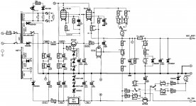
I think I've decided to go a different route,I found an article in AudioXpress on regulated supplies and found one that's a better performer,and has been tested. I've re-drawn the schematic for expresspcb. The author didn't mention lifting the heater on the pass tube,so I will do that if it's needed.
Attachments
Last edited:
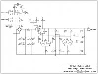
In the original schematic, it looks like V2 (EC92) is supposed to work as the error amplifier. However, it doesn't have any voltage reference and will always operate with a positive Vgk. Not what you want...
The 0~-70 V output isn't regulated either. I honestly don't see the point of the emitter follower T2. Why would you take the supply output off the base but run the meter off of the lower impedance emitter?
There are better ways to build tube power supplies. Have a look at Designing Power Supplies for Tube Amplifiers by Blencowe for example.
You can also look at this thread: http://www.diyaudio.com/forums/tubes-valves/183164-high-voltage-regulators-maida-zener.html
I went through quite a few regulator topologies before landing on the two I have on my website.
For a variable supply, I use a high-voltage transformer fed from a variac. Works great. No thermals to worry about. No regulation either, but good enough for most experiments.
~Tom
Last edited:
Sorry... Didn't see Post #13 until I after I'd written my post above.
With the dual differential pair, it's a very "semiconductor" approach to a tube regulator. I don't see any reason it shouldn't work, though.
You'll need to check the data sheet for your pass tube of choice to figure that out. You'll have to select a voltage that ensures the pass tube doesn't have its Vhk violated at any output voltage.
~Tom
I think I've decided to go a different route,I found an article in AudioXpress on regulated supplies and found one that's a better performer,and has been tested.
With the dual differential pair, it's a very "semiconductor" approach to a tube regulator. I don't see any reason it shouldn't work, though.
I've re-drawn the schematic for expresspcb. The author didn't mention lifting the heater on the pass tube,so I will do that if it's needed.
You'll need to check the data sheet for your pass tube of choice to figure that out. You'll have to select a voltage that ensures the pass tube doesn't have its Vhk violated at any output voltage.
~Tom
To use the 12AT7 at 6.3V you need to connect Pins 4&5, not 4&9. In your schematic half of the heater is shorted.
I've worked on several Dynaco Fm3's and it has a mixture of
6 and 12volt tubes, this is I believe a parallel connection.
In the original schematic, it looks like V2 (EC92) is supposed to work as the error amplifier. However, it doesn't have any voltage reference and will always operate with a positive Vgk. Not what you want...
The 0~-70 V output isn't regulated either. I honestly don't see the point of the emitter follower T2. Why would you take the supply output off the base but run the meter off of the lower impedance emitter?
There are better ways to build tube power supplies. Have a look at Designing Power Supplies for Tube Amplifiers by Blencowe for example.
You can also look at this thread: http://www.diyaudio.com/forums/tubes-valves/183164-high-voltage-regulators-maida-zener.html
I went through quite a few regulator topologies before landing on the two I have on my website.
For a variable supply, I use a high-voltage transformer fed from a variac. Works great. No thermals to worry about. No regulation either, but good enough for most experiments.
~Tom
Thanks for the suggestions, I'm glad you mentioned the book, I bought that
Book a few months back for my iBooks app, I haven't finished it yet
But it is a marvelously well written book, as soon as I get my new iPad I will try and finish it, it's hard to read on an iPhone!! I also have Morgan Jones' book.
On Kindle that is an in depth read.
- Status
- This old topic is closed. If you want to reopen this topic, contact a moderator using the "Report Post" button.
- Home
- Amplifiers
- Tubes / Valves
- Regulated Power Supply using 6550