Why give credit to that rubbish design the RH - yours is substantially better. However it would be better if your driver were running at least 5mA.
I use direct coupling from a pentode in my PP designs. but I avoid the big cathode resistor by using an input transformer and a negative rail.
Shoog
I use direct coupling from a pentode in my PP designs. but I avoid the big cathode resistor by using an input transformer and a negative rail.
Shoog
Last edited:
Why give credit to that rubbish design the RH (...)
Shoog
Harsh words, considering the fact that undisputed designs are almost nonexistent. Nature of the trade I guess – if one follows it long enough, one can witness circuit designers coming up with 'my precious' only to, with time, feel disenchanted and move onto something else... Consumed by the road to and not the destination.
Of all RH84 critics it's you and revintage that seemingly sound as if it were something personal.
Harsh manner, considering the fact that Kitic (wrong or right) is not able to respond...
Harsh manner, considering the fact that Kitic (wrong or right) is not able to respond...
Why is he not able to respond?
Harsh manner, considering the fact that Kitic (wrong or right) is not able to respond...
Maybe because he has been banned from every discussion board he took part in due to his very disagreeable personality.
The designer here has ditched the distortion generating triode driver in favour of the pentode - this is what Kitic should have done in the first place and why honoring Kitic for a superior design is the wrong thing to do.
Shoog
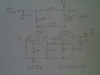
I referred to the RH design because it seems to have a fan base, and because I think the basic idea of a SE EL84 with local feedback is sound, but the design could be improved. I could as easily called it a Mullard 3-3 variation with Schade feedback. I consider this design an improvement over the Mullard since I don't starve the driver like it did.
Ultimately, I intend for this to become a direct coupled E-linear amp with the load and feedback resistors replaced by a single resistor connected to the screen tap on the output transformer.
Ultimately, I intend for this to become a direct coupled E-linear amp with the load and feedback resistors replaced by a single resistor connected to the screen tap on the output transformer.
Why give credit to that rubbish design the RH - yours is substantially better. However it would be better if your driver were running at least 5mA.
I use direct coupling from a pentode in my PP designs. but I avoid the big cathode resistor by using an input transformer and a negative rail.
Shoog
Would you care to explain why you consider it rubbish?
Paul, you are drawing too little current through the driver. The B+ value is not shown on the schematic, but if the output tube draws 40mA this means just 40V under the cathode of the output tube and mot more than 50V on the anode of the driver. It is lowish for the 6SJ7, and while the design is on the right path, it needs a lot of optimizing. Higher voltages, Rk of at least 2k for the output tube. If you insist on using a pentode driver, than use the second grid to control current draw and voltage drops.
And, thumbs up for crediting where credit is due, Paul - otherwise you end-up being a copycat.
Because its a distortion generator.
Shoog
Would you care to explain why you consider it rubbish?
I think "rubbish" is maybe a bit too harsh. I'd put the design in the "quick 'n' dirty category. Good enough for an AM ham rig plate modulator, or a gee-tah amp. High end, it ain't. Here's the original design: RH-807. There's a lot wrong with this. One is using a difficult final as a SE. The 807 likes to make nasty sounding, high order harmonics. It does require the addition of local NFB to help tame it, but also needs gNFB to really take the edge off. It's even worse in SE as you don't have the cancellation of even order harmonics in a SE. (I did a design that uses 807 finals, but that was PP, included both local and global NFB, fixed bias, and active screen regulation. The type can give excellent sonic performance, but you have to work at it.)
The thing also uses an unbypassed, 10K series dropping resistor for the screen supply. This is hideous. Running pents as pents requires screen voltage regulation. (You can get away with it for small signal voltage amplification in low level stages since the plate current variations are much smaller than what you see with large signal finals.) At the very least the screen needs a stiff voltage divider with a large enough bypass capacitor. The 807 has screen voltages close to what you can get from a series string of VR tubes, and that's what he should have used at the very least. Active regulation is better still. What you have here is absolutely the worst possible screen supply.
The RH-807 is an FX box, not an amp. Maybe suitable as a guitar practice amp, but that's about it.
Why give credit to that rubbish design the RH - yours is substantially better. However it would be better if your driver were running at least 5mA.
I use direct coupling from a pentode in my PP designs. but I avoid the big cathode resistor by using an input transformer and a negative rail.
I figure ~3 -- 5mA for the driver is about right. The other possibility is to ditch the singleton pentode, substitute a triode/pentode like the 6KE8 and use the triode as a cathode follower grid driver. He could also go with the "E-Linear" design that uses an OPT with an Ultralinear tap-off. The main problem here is that DC connection in the lNFB loop that puts limits on the feedback resistor. Maybe make that an AC only connection for greater flexibility in selecting plate resistors for the driver? (E-Linear would accomplish the same thing.)
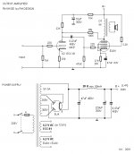
Let's look at the original RH84 (schematic uploaded) and look for sources of distortion.
We start with the previously mentioned unbypassed g2 supply. Also, it's well established that regulating pentode g2 B+ reduces distortion. Stacking 0A2 and 0B2 gas discharge regulators disposes of the g2 issues.
The 12AT7/ECC81 has linearity problems. The unbypassed cathode resistor is an attempt to deal with that. However, the 22 KOhm load resistor is too small for a setup using a bypassed cathode resistor and it is woefully undersized for a situation where degeneration raises RP. CCS loading the 'T7 section might salvage the situation, but I'm going to suggest the 6GK5 as the voltage amplifier. A 22 KOhm load resistor is satisfactory for use on a 6GK5's anode.
The 1 MOhm voltage amplifier grid to ground resistance is way too big, as it will interact with the CMiller of a triode to roll HF info. off. 470 KOhms is OK, when a pentode is the voltage amplifier. 150 KOhms is (IMO) about right for the sort of triodes being discussed.
Finally, I would take a page out of Stu Hegeman's book and use a small amount of GNFB. A single red LED should be fine for biasing the 6GK5 and a cap. would not be needed in the voltage amplifier's cathode circuitry.
Attachments
The B+ value is not shown on the schematic, but if the output tube draws 40mA this means just 40V under the cathode of the output tube and mot more than 50V on the anode of the driver.
The B+ is 300v, and the output tube draws about 48ma. This with the 5ma the screen draws biases the output tube at 53v. The screen of the input tube sits at 40v, and its plate is about 48v. For comparison the Mullard 3-3 design runs an ef86 with 20v on the plate, and 29v on the screen.
I've been told a couple of times that this design, and another similar to it draw too little current through the input tubes. It is certainly lower than typical, and if the screens were at the usual voltage, the tubes would be operating in a fairly non-linear region. But, according to the transconductance curves for the screen voltage I am using, the tubes should remain in a fairly linear region of operation through to full output. Also, since the output tube is operating as a pentode, miller capacitance and slew rate shouldn't be an issue. For comparison again, one version of the Mullard 3-3 ran about .1ma through the input tube.
One possible issue I have thought of, is that I am not sure at what bias voltage the grid of a 6SJ7 begins to conduct. This design biases at just under one volt, and for some tubes that could be too low. If you can think of any other issues I have overlooked, I would be glad to know about them.
Because its a distortion generator.
Shoog
In a way, that might just be a good quality of this amp - if it (driver tube) generates even order distortion, this probably leads to distortion cancellation in interaction with the output tube.
I assume you mean that the triode driver is a distortion generator, of course, since you seem to like the idea of a pentode driver.
What arguments do you have to complement that a pentode (let's say 6AU6) would be a better driver than a triode (let's say 12AT7)? Can you show us some simulation or graphs... anything?
I think "rubbish" is maybe a bit too harsh. I'd put the design in the "quick 'n' dirty category. Good enough for an AM ham rig plate modulator, or a gee-tah amp. High end, it ain't.
I would not agree with that - it seems that a lot of work and insight has gone into that design. Quick and dirty, those might be the copycats appearing from time to time. High End? That mostly depends on components used, I hear.
Here's the original design: RH-807. There's a lot wrong with this. One is using a difficult final as a SE. The 807 likes to make nasty sounding, high order harmonics. It does require the addition of local NFB to help tame it, but also needs gNFB to really take the edge off. It's even worse in SE as you don't have the cancellation of even order harmonics in a SE. (I did a design that uses 807 finals, but that was PP, included both local and global NFB, fixed bias, and active screen regulation. The type can give excellent sonic performance, but you have to work at it.)
Difficult final? The 807 is in essence a 6L6 with separate anode connection, enabling higher differences in potential between anode and g2 (arcing problems with 6L6 in some class C operation conditions). ALL beam tetrodes tend to make nasty sounding high order harmonics - and you seem to have missed the point that the short NFB path is there to adress this issue. If I recall correctly, it was something like "the sound of a triode with the power of a pentode".
It seems that some people have inlcuded switches in their RH amps to be able to check the difference between triode strapped without NFB and pentode with the proposed feedback. All have reported that the sound is basically the same in triode and pentode RH mode, with a difference in power and bass definition (better in pentode mode).
The thing also uses an unbypassed, 10K series dropping resistor for the screen supply. This is hideous. Running pents as pents requires screen voltage regulation. (You can get away with it for small signal voltage amplification in low level stages since the plate current variations are much smaller than what you see with large signal finals.) At the very least the screen needs a stiff voltage divider with a large enough bypass capacitor. The 807 has screen voltages close to what you can get from a series string of VR tubes, and that's what he should have used at the very least. Active regulation is better still. What you have here is absolutely the worst possible screen supply.
The 10k dropping resistors seem to be quite common in many schematics featuring the 807. If you recall, the 807 was indeed meant to operate with a large difference in voltage between anode and g2. Why hideous?
It is not at all true - neither found in literature, nor in general schematics, not even when checking out "Hi-End" amplifiers schematics (the Hi-End issue is a matter of opinion), and of course not at all necessary, to have regulated screen voltages with pentodes, or tetrodes, or beam tetrodes. While some form of regulation might be beneficial, or not, it is NOT AT ALL MANDATORY, as you put it, and only novices who have built very few amps and still know very little would read that statement without objecting. Actually, this is a good way to mislead others. Why are you doing this? Is it that you do not know, or else?
VR tubes are not all that common nowadays. A good example where VR tubes were used in an 807 SE amp is the Gordon Rankin design "fixing" the g2 voltage on both output tubes - that detail, besides looking good indeed (the glow of 0D3 and 0C3, if I am not mistaken) allegedly leads to very good bass. As a matter of fact, VR tubes are also known to generate a lot of noise, and some might object to noise being injected through the g2 on both channels.
Active regulation means that you will hear the regulator in your circuit. Just like the above example, some might object that it is not a good way to go.
But the most important issue to stress is: g2 regulation is not at all necessary, and was never meant to be done when those tubes were "invented" or used like we use microprocessors or transistors in our everyday life.
The RH-807 is an FX box, not an amp. Maybe suitable as a guitar practice amp, but that's about it.
That is your own subjective opinion, you know. Most guitar players would probably not agree - guitar amps are built with different characteristics in mind, and the characteristic distortion pattern of the RH amps (low distortion until the point where odd order distortions start to dominate, which of course happen relatively abruptly at some point when the critical output power has been reached, i.e. clipping) is not suitable for the purpose or taste of most guitar players. I guess you do not know what an FX box is... and also guess you do not play any instrument so you do not know what "makes" a good instrument amplifier.
BTW, your statement means that guitar amps (practice amp, ha!) are bad and musicians have no ears? It's an insult both to guitar amps and guitar players... and without them we would not have two things that are important to us, I believe: a) music; b) tubes (current production).
In the end, I would like to invite you to produce some simulations, links, or diagrams confirming your statements.
Let's look at the original RH84 (schematic uploaded) and look for sources of distortion.
We start with the previously mentioned unbypassed g2 supply. Also, it's well established that regulating pentode g2 B+ reduces distortion. Stacking 0A2 and 0B2 gas discharge regulators disposes of the g2 issues.
Just as in my previous post, stacking of VR tubes is one approach, stacking zeners might be another, active regulation a third approach. But neither is without potential fault (introduced noise might be one example) and the issue here is whether additional distortion tackling is necessary.
I believe you should take as well into account that one 10k resistor costs a lot less than VR tubes, sockets, regulators, etc. and is far simpler to implement, particularly for a first-time builder, or a novice. On the other hand, for a more experienced builder, the gain (i.e. possibly lower distorition) might not be worth the hassle or expense of adding all the mentioned elements.
Regarding the bypassing, maybe it would be worth to mention that bypassing or setting the g2 voltage with voltage-divider resistors and bypassing is not necessary with power tetrodes/pentodes, particularly due to the relatively low resistor values involved. Bypassing is important (and necessary) with small signal pentodes where g2 is set with high valued resistors, like 100k to 1meg, and the bypass is necessary to allow for frequency response, etc. These details are neglected nowadays since most have very little knowledge of tubes, pentodes in particular, and due to the triode hype there are very few pentode based preamplifier and driver examples in current DIY circles - most pentodes tend to be used as triodes (particularly in the small signal "department") and thus good examples for the bypassing issue and setting the correct values for g2 are not easy to find. I believe you should know that.
The 12AT7/ECC81 has linearity problems. The unbypassed cathode resistor is an attempt to deal with that. However, the 22 KOhm load resistor is too small for a setup using a bypassed cathode resistor and it is woefully undersized for a situation where degeneration raises RP. CCS loading the 'T7 section might salvage the situation, but I'm going to suggest the 6GK5 as the voltage amplifier. A 22 KOhm load resistor is satisfactory for use on a 6GK5's anode.
I am not aware that the 12AT7 has any linearity problems. Maybe linearity is not the same to those who read about it in literature and those who read about it or heard about it in DIY circles (no pun intended to those who actually know what linearity is). Anyway, this is not about linearity, but the application of a give tube for a given task. From what I know and read and learned, to do the task required from a driver in those RH amps, a tube has to have a combination of high transconductance and high mu with a relatively high Rp - which is why the 12AT7 is a good choice.
While CCS loading might be a good idea, it is actually not realistic and would yield very little given the fact that part of the current drawn by the driver tube comes from the Rfb resistor. A good CCS would need to pass all the current needed for the driver tube, and then some more to be discharged through a resistor (check out the work of Alan Kimmel) - and I believe all that would have been rendered invalid by the Rfb adding current which is not coming from the CCS. Not to mention the fact that the real treat of a CCS above the anode is not linearity per-se but higher gain than achievable with a resistor (would be achievable with a choke, but with other intrinsic problems). It does not look that RH type amps would benefit from higher gain in the driver section.
Last but not least, the cathode resistor of the driver tube has to be unbypassed to allow the feedback to work - if you bypass the resistor, there will be no feedback through the Rfb, which is the main feature of the RH amps, if I am correct. The cathode resistor is set to a value to draw current (automatic bias for the driver tube) and set some level of gain for the driver tube, which when combined with the values of the anode resistor, and the feedback resistor, performs a given task in the amplifier. Changing the value will change everything, from gain to current draw to operating point, etc. Cathode degeneration seems to be the least important issue here, since with a bypassed cathode resistor the whole circuit looses its purpose. You should have noticed that from the schematics.
The 1 MOhm voltage amplifier grid to ground resistance is way too big, as it will interact with the CMiller of a triode to roll HF info. off. 470 KOhms is OK, when a pentode is the voltage amplifier. 150 KOhms is (IMO) about right for the sort of triodes being discussed.
Finally, I would take a page out of Stu Hegeman's book and use a small amount of GNFB. A single red LED should be fine for biasing the 6GK5 and a cap. would not be needed in the voltage amplifier's cathode circuitry.
The 1 meg resistance is the maximum allowed resistance for the EL84 and thus causes no problems. The Miller effect of the pentode connected EL84 is quite negligible, since the input capacity of pentodes is way lower than the input capacity of triodes, particularly the (old) DHTs. This issue has already been pointed out in several replies in several forums were those amps were discussed - the Miller effect is not an issue.
Regarding the single red LED, just as above, let me remind you that if the cathode resistor is bypassed, there is no feedback, i.e. no RH amp circuit. The same is true of LEDs or other CCS solutions, like LM317.
You mention wanting to use a 6GK5, and some GNFB (I presume you refer to feedback taken from the output side of the output transformer). You might wish to show us what you mean by presenting a calculation, or a simulation with results? Otherwise, it's just a "smart" idea.
As I understood, the point with RH amps and the Rfb is that feedback is applied in a more direct fashion, excluding output transformers from the equation, which should be beneficial (IS beneficial, actually). Now, adding some negative feedback can be achieved by setting a lower Rfb value, if further negative feedback is leading us somewhere - but that would interfere with the ability of the driver circuit to drive the output tube. I believe that you are aware what types of distortion can be addressed with negative feedback? Thus, if we have already addressed this type of distortion, why would we need additional feedback?
Last but not least, I would like to comment on the schematics linked or attached as examples: it seems that you are not aware that there have been further improvements and revisions on the RH amps, in part addressing the issues you mentioned - this would be the link to check:
RH Amplifiers
Finally, I must say that all the comments and criticisms given in the above few posts are subjective to say the least. Such undocumented statements seem to point out lack of knowledge and understanding - more than eventual flaws in the design of those amps.
I agree with most of the criticisms so far but they do not really address the fundamental design flaw.
Fundamentally the RH807 shows a prefound lack of understanding of what is involved in plate to plate feedback (Schade). The input grid of a Schaded pentode represents an extremely low impedance input node. The only way to adequately drive such a node (linearly) is with a CCS. There are two options available - another pentode which approaches a CCS and is well able to drive a low and variable impedance load, or power drive which achieves the same through the CCS nature of a MOSFET.
A triode cannot perform this service and will distort badly at any reasonable power output. This has been measured repeatedly with the RH designs.
Because of the low impedence of the input grid the driver needs good reserves of DC standing current in order to be able to produce the AC current swing without running out of steam. The 6AU6 works OK at about 5mA and this has proven adequate in my Tabor clone, however its difficult to bias up if you want to run more DC. I am currently putting to bed a Schade PP amp (direct coupled) and have attempted to push 10mA through the 6AU6, it only gives about -1V of input bias which is inadequate. A small power pentode seems to be in order for driver duty when attempting to run at these currents.
This whole subject has been discussed many times before, with Alex Kitric been involved (until he stormed off when he couldn't defend his flawed design decisions), by people of far better expertise than my own, and who can crunch the fundamental numbers to prove that this design stinks.
The fact that it has become so popular is proof that many people who venture into valves only want an amp with high (but pleasant) distortion. Not for me.
Let it be said - my first valve amp was a RH807 variant.
Shoog
Last edited:
Just thinking that myselfAlpha Kentaury...Is that you Alex? Somthing smells fishy....
Shoog
I have built a few RH84, some i liked and some i did not. It seemed that the cheaper the parts the more I liked it...
I have also built a few similar amps with Schade feedback with an EL84 using a 6AU6 as a driver and also a 6688. Was not really blown away by either of them for some reason;
I dont have any equipment for measuring but I am willing to bet the distortion spectrum had a role to play in my lack of excitement for either.
Built a triode-strapped 6V6 driven by a CCS-LED loaded 6SN7 and I was all smiles
- Status
- This old topic is closed. If you want to reopen this topic, contact a moderator using the "Report Post" button.
- Home
- Amplifiers
- Tubes / Valves
- RH 84 Variation: Direct Coupled Pentode