I have a 33k in there. Works fine. For the rest I have followed the schematic.The 1 MOhm voltage amplifier grid to ground resistance is way too big,
I'm sure it is.Alpha Kentaury... Is that you Alex?
Perhaps. But I am very happy with my RH84. Not sure how much the small console output transformers are responsible for...but I really really like the RH84 in my setup. So much so that I've taken the Baby Huey EL84 amp out of my system. I'll soon use that chassis to build another ppEL84 when I've finished the other amps that are in the pipeline.Because its a distortion generator.
I agree with most of the criticisms so far but they do not really address the fundamental design flaw.
Fundamentally the RH807 shows a prefound lack of understanding of what is involved in plate to plate feedback (Schade). The input grid of a Schaded pentode represents an extremely low impedance input node. The only way to adequately drive such a node (linearly) is with a CCS. There are two options available - another pentode which approaches a CCS and is well able to drive a low and variable impedance load, or power drive which achieves the same through the CCS nature of a MOSFET.
1) There is a fundamental difference between Schade feedback and plate to plate feedback. Schade feedback is voltage only and not directly related to other devicies preceeding the output tube (read carefully the Schade text on tetrodes he wrote for RCA). A tetrode or pentode tube in Schade configuration actually presents curves that are more or less similar to triode behaviour or triode curves - here's a link for your enjoyment and education:
307a with schade feedback (Part II) | Bartola Valves
2) Plate to plate feedback is both current and voltage. Now to assess correctly the other parts of this equation, you would need to know what would the input impedance of the pentode output tube in this circuit be. The most important part is how does the circuit work, and what are the results of the operation of the circuit - not the assumptions about input impedance and the ability to drive it. Furthermore, CCS, already disqualified in my previous post because there is current being drawn through the Rfb, is not important or necessary for a tube to be able to drive a given load - but the current it draws is. I.e. too low current drawn through whichever concotion, be it CCS or choke or resistor, and the triode or pentode will not be able to drive adquately a difficult load. Anyway, this is not the case with RH amps, and the CCS has nothing to do with this story.
I would say it's actually you who do not have enough knowledge or do not understand the principles above mentioned (Schade feedback, plate to plate feedback, CCS).
A triode cannot perform this service and will distort badly at any reasonable power output. This has been measured repeatedly with the RH designs.
This is an interesting statement. Besides the fact that whether a device will or will not be able to perform the service mentioned (drive the output tube) depends on the current it draws (not whether it draws current through a CCS or choke or resistor, nor whether the device is a triode, pentode, or FET) - and in the case of the RH amps and the "notorious" 12AT7 the tube does draw an adequate current because of its characteristics, i.e. transconductance, Rp, and mu - what is mostly striking is the fact that I have never seen any measurements of RH amps published anywhere on the net, yet alone that these measurements (an FFT analyzer would suffice, I believe) have shown distortions caused by the driver tube (among other reasons, because they have never been performed and/or published anywhere).
Please correct me if I am wrong... I have seen a lot of published RH amplifier simulations, but no measurements documented, particularly by those who criticize the design with such conviction and self-assuredness.
The 6AU6 works OK at about 5mA and this has proven adequate in my Tabor clone, however its difficult to bias up if you want to run more DC. I am currently putting to bed a Schade PP amp (direct coupled) and have attempted to push 10mA through the 6AU6, it only gives about -1V of input bias which is inadequate. A small power pentode seems to be in order for driver duty when attempting to run at these currents..
A 6AU6 would indeed be a good driver cadidate for an "all pentode" RH amp. In order to make it work as it should in the circuit where it is required, one would need to be able to combine idea, knowledge, and means.
From what you wrote above, it can be understood that you are not able to design an amplifier "academically", i.e. without touching the parts. Your process is more like "trial and error", let's take this resistor and see if it works, where you can decide on whether it works based on being or not satisfied with the results.
Thus your statements are quite bold and unsubstantiated. You are of course free to enjoy your tubes and amps in whichever way you like, and you are also free to express your own opinions, good or bad. BUT when it comes to expressing your opinions, it should be taken into account whether they are:
a) subjective, b) not quite knowledgeable, c) unsubstantiated.
Not to mention your language: "stinky", "rubbish"... maybe they are not F words, but nevertheless I guess in your native tongue such language is defined as "faul". Not the type of language we civilized people should use in forums, eh?
This whole subject has been discussed many times before, with Alex Kitric been involved (until he stormed off when he couldn't defend his flawed design decisions), by people of far better expertise than my own, and who can crunch the fundamental numbers to prove that this design stinks.
Well, here you have confirmed what I wrote just above - your, to put it that way, lack of expertise. Regarding the "storming off" part, I wouldn't know, but I guess the guy is not participating in DiyAudio because he got banned. Actually, I have it on good authority that after being temporarily banned, he has requested to be banned "for life" because he was not happy with the DIY forums community. Anyway, all those threads are still accessible, maybe someone can point out the moment when he gets stormed off by some mighty authority who lets him know his ways about all this Schade feedback and stuff, showing results of measurements and simulations, and other solid arguments (yeah, like that has happened).
The fact that it has become so popular is proof that many people who venture into valves only want an amp with high (but pleasant) distortion. Not for me.
Let it be said - my first valve amp was a RH807 variant.
You got it all wrong about the distortions - actually, the RH amps have very low distortions up to a point where the OUTPUT device gets into clipping (after all, each and every device will eventually get to the end of its capability). I guess what those who like it find appealing is the sound (maybe has something to do with a superior dumping factor?), and the fact that clipping does not occur before it is supposed to happen with the device in question (we are talking 12W dissipation pentodes, not KT120 or 813).
When you mention "variant" it must be that you never built the RH807 as it was meant to be, but changed circuit values, probably tried something with a pentode driver - if you did not like it, it was not the RH807s fault, but your own.
I have built a few RH84, some i liked and some i did not. It seemed that the cheaper the parts the more I liked it...
Maybe it has nothing to do with the parts you paid more... each and every tube has it's sound, and using more expensive output transformers, for instance, has probably left you sore-tasted if the cheaper version used a Philips 6201 against that Telefunken ECC81 you might have used in the more expensive version... or a matter of rectifier (American octal types sound better than European noval types)... just guessing.
I have also built a few similar amps with Schade feedback with an EL84 using a 6AU6 as a driver and also a 6688. Was not really blown away by either of them for some reason;
I dont have any equipment for measuring but I am willing to bet the distortion spectrum had a role to play in my lack of excitement for either.
During the years there have been several copycat designs, possibly some have tried to use the 6AU6... of course, a schemtics for an "all pentode" RH84 exists... and it probably does not match what you have built.
Furthermore, the sound of RH amps seems to depend on the sound inherent to the driver tube used. Maybe it was your ECC81s sounding better than your 6AU6s?
Built a triode-strapped 6V6 driven by a CCS-LED loaded 6SN7 and I was all smiles")
That is most probably true and quite easy to do. Plus, it is quite easy to find good sounding 6SN7s - the same is true of 6V6s. But it has 1.5W output power (triode strapped), which might not be important to you if you own very efficient speakers and/or do not listen to loud music, or prefer less dynamic music genres. And most 2A3 or 6B4G amps would easily beat it, both in output power (2.5W) and sound - unless it was an RH6V6 with 4-5W output power and some dumping factor under its sleeve
I have a 33k in there. Works fine. For the rest I have followed the schematic.
According to the datasheets, 1meg is OK. If you feel uncomfortable with that value, you can always opt for 330k or 470k... 33k is too low, and is probably compromising your bass response... maybe you should try changing it for a 330k resistor?
Basically I just used whatever I found first in my parts box that I knew would be ok. I have to rebuild my RH84 anyway because I want to use chokes in the psu and currently the chassis is too small....I'll use a 330k next time. But....I have no problems with my bass response.If you feel uncomfortable with that value, you can always opt for 330k or 470k
Last edited:
Difficult final? The 807 is in essence a 6L6 with separate anode connection, enabling higher differences in potential between anode and g2 (arcing problems with 6L6 in some class C operation conditions). ALL beam tetrodes tend to make nasty sounding high order harmonics - and you seem to have missed the point that the short NFB path is there to adress this issue. If I recall correctly, it was something like "the sound of a triode with the power of a pentode".
Hey Alex, welcome to the forums!
I have experience with using 807s. (Vixen Main Schemo) I measured the open loop output I was getting with the "Twin-T" test, and the residual was as advertised in the spec sheet, and actually was a bit less that advertised. However, that residual looked almost like a sawtooth at three times the frequency. That means ESSSSSS-loads of high order harmonics. The ear heard what the o'scope showed: running the Vixen open loop was difficult to listen to for any length of time. Lots of nasty, dissonant distortion that led to listener fatigue rather quickly. And, yes, I have O. Schade's original "white paper" on the design, and followed his suggestion to include local NFB. He knew what he was talking about, and that cleared up a lot of the mess. All that was required was enough gNFB to take the edge off.
As for your contention that "all" beamers make this type of distortion, it's nonsense, pure and simple. The 6BQ6 (TV horizontal deflection power beamer) did not make that kind of distortion. When testing the Le Renard design open loop, the level of residual distortion was higher, but nearly a pure sine wave at three times the frequency. It was almost all H3 with a trace of H5 and higher. Open loop, the Le Renard was much easier to listen to, the sound being mainly overly "aggressive" without that pentode nastiness unless played at nearly the clipping point. This design didn't require lNFB, and just enough gNFB to take the "edge" off. The 6V6 is quite similar, and I have stated that the 6BQ6 is basically a 6V6 that can pump out nearly three times the power.
Others here (especially TubeLab) have confirmed these results.
The 10k dropping resistors seem to be quite common in many schematics featuring the 807.
Every one I've seen has been a Class C RF amp, and the screen was bypassed to ground.
It is not at all true - neither found in literature, nor in general schematics, not even when checking out "Hi-End" amplifiers schematics (the Hi-End issue is a matter of opinion), and of course not at all necessary, to have regulated screen voltages with pentodes, or tetrodes, or beam tetrodes. While some form of regulation might be beneficial, or not, it is NOT AT ALL MANDATORY, as you put it, and only novices who have built very few amps and still know very little would read that statement without objecting. Actually, this is a good way to mislead others. Why are you doing this? Is it that you do not know, or else?
I'm doing it because it's the damn truth. There were a good many designs created back in "the day" to get around this problem. One was types like the 6V6 or 50C5: designed to operate their screens at the same voltages as the plates. There was also the Ultralinear scheme to avoid the need for regulation. I have also seen a schemo of a professional amp built for theatres that definitely included screen grid regulation for the screens of the 807 finals.
VR tubes are not all that common nowadays.
Then how come I have no problems ordering them on-line or picking them up at hamfests?
VR tubes are also known to generate a lot of noise, and some might object to noise being injected through the g2 on both channels.
The noise from VR tubes is a helluvalot less bothersome than that from Zeners.
Active regulation means that you will hear the regulator in your circuit. Just like the above example, some might object that it is not a good way to go.
Pure audiophoolery from the same yutzes that "think" NFB is the Spawn of Satan. Active regualtors are a type of servo, and depend on NFB for their operation. If you can actually hear one, then it's a very bad design that is likely oscillating. You either need to fix your design, or improve your construction skills. Otherwise, no, just no: you won't hear it at all.
But the most important issue to stress is: g2 regulation is not at all necessary, and was never meant to be done when those tubes were "invented" or used like we use microprocessors or transistors in our everyday life.
If it was never meant to be done, then how come there are so many schemos of both AF and RF amps that include it? For power finals, nailing down that V22 is indeed important, as is a low impedance path to AC ground to get the AC off the screen, as it can, and does, act like a second control grid. What you hang on the screen is highly important, and will have an effect on the transfer characteristic.
BTW, your statement means that guitar amps (practice amp, ha!) are bad and musicians have no ears? It's an insult both to guitar amps and guitar players... and without them we would not have two things that are important to us, I believe: a) music; b) tubes (current production).
In the end, I would like to invite you to produce some simulations, links, or diagrams confirming your statements.
Now you're just making stuff up here. This merits no further comment. As for your personal attacks, that speaks for itself.
PS: You misspelled Centauri.
An externally hosted image should be here but it was not working when we last tested it.
I agree with most of the criticisms so far but they do not really address the fundamental design flaw. Fundamentally the RH807 shows a prefound lack of understanding of what is involved in plate to plate feedback (Schade). The input grid of a Schaded pentode represents an extremely low impedance input node. The only way to adequately drive such a node (linearly) is with a CCS. There are two options available - another pentode which approaches a CCS and is well able to drive a low and variable impedance load, or power drive which achieves the same through the CCS nature of a MOSFET.
I didn't mention it since it seemed so obvious. The main problem with this type of lNFB is that the effective resistance of Rfb is decreased for the same reason Crt is effectively increased: Miller Effect. Triodes simply do not like heavy plate loads, and protest by generating both low gain and high distortion.
The fact that it has become so popular is proof that many people who venture into valves only want an amp with high (but pleasant) distortion. Not for me.
Let it be said - my first valve amp was a RH807 variant.
Shoog
Listener preference. I would never say "Don't build this design" because you can never tell. Some might like it, others think "Meh, nothing special", and others might think: "YUCK!" It's always a case of try and listen, and that's always the case for any design. It all comes down to preference, what kind of music you like, what speeks you have, etc, etc, etc. If it were that easy, we could simply have the schemo for the "Perfect Amp" and close down these forums for good. Not. Gonna. Happen.
I have slapped together some "hen scratches" that cover some of the points that have been raised. Given the speed at which this was done, errors are likely. Examine and correct, please.
The Triad power transformers shown are inexpensive and have dual primaries, which allows almost everybody to use the ideas presented.
The brute force method of phase compensation was chosen to allow a builder whose instrumentation is limited to a good VOM to execute the project.
"Lay on MacDuff!"
The Triad power transformers shown are inexpensive and have dual primaries, which allows almost everybody to use the ideas presented.
The brute force method of phase compensation was chosen to allow a builder whose instrumentation is limited to a good VOM to execute the project.
"Lay on MacDuff!"
Attachments
First and foremost, I really have very limited time for posting on forums. Furthermore, it does not seem to produce results, because other people seem to have all the time in the world, and continue replying without producing what was asked for in my posts.
1) This is a nice story, but besides confirming in the end that you have solved the problem with negative feedback, you have not produced any evidence in the form of screenshots or links to screenshots, etc. It remains thus unsubstantiated, although there is no reason not to believe that there have been high order harmonics in that push-pull design.
2) If you have solved the problem with an effective amount of gNFB, why would an adequate amount of local NFB (anode to anode) not be able to solve this or similar problems? After all, local NFB does not include the output transformer into the loop and is therefore less prone to oscillation... etc.
1) As far as I can see, again similar output stage, push pull, etc. as above. Again without any "evidence" besides your interesting story.
2) Again it seems that negative feedback seems to be the cure?
3) Again global NFB instead of local, maybe because it is difficult to calculate, or because it is difficult to calculate without simulating? Some sort of evidence is welcome if you intend to further this and similar issues, otherwise I will not loos any more time on replying.
1) Maybe because the 807 was meant primarily for use in public address and RF equipment? So is the 307A (WE states that the 306A was meant for audio application) but it can be used nevertheless in pentode mode in amplifiers with excellent results:
RH Amplifiers: RH-307A
2) For details on the 807 tube I suggest everyone who has not yet had the pleasure of reading it to follow the link to the STC datasheet: RetrovoxSTC807.pdf
3) Regarding screen bypass, I already said that it is something that is usually done with small signal tubes. I will not comment this further, but can only invite all interested to read some literature on that subject, plenty can be found on the net.
Can you produce some links to some reputable source that states IT MUST BE DONE, OTHERWISE... ?
Back in the days, as you say, if you were to tackle the issue flawlessly, you would have had a separate power supply for g2 - just take a look at the above linked STC datasheet.
Furthermore, Ultralinear was not "invented" back in the days, but slightly later - whichever came first, Ultralinear bears a potential problem of higher g2 potential than anode potential, which might or might not cause problems, depending on the tube, etc. Neither flawless nor universally applicable, and requiring an additional tap... and the percentage of windings (and subsequent feedback arrangement between anode and greed) also remains a disputed issue.
Probably because you are so lucky to have been born and live in the US of A where, among other things, hamfests exists and people can meet and swap.
VR tubes can of course be ordered from sellers on the net, but all that I have already wrote on the argument remains:
1) You need the tube (tubes),
2) You need the socket (sockets),
3) You need the place for those tubes and sockets,
4) You might not be able to source them (tubes and sockets), you might not have the place where to put them (small amp chassis, many build RH amps without a rectifier because they do not have one, or because it takes up space... let alone VR tubes).
That said, I like the glow of VR tubes and intend to experiment with them because they look better than zeners and I happen to own a few.
And I will not reply to this subject, as well.
Depends on the application, and is widely disputed. I do not think this is a subject worth pursuing further, at least for the moment.
This is not actually true. Active regulators have a different output than unregulated (choke first, for example) power supplies. While most SS regulators are much more effective in filtering the ripple, and stabilizing the voltage, they have an inherent noise, which mostly originates from the voltage reference. The better the voltage reference, the less noise. Of course, active elements also produce "noise". Whether you hear this noise or not (being able to hear, being disturbed by it, etc.) is a different issue, but the noise of regulators is widely documented on the net.
What matters here, anyway, is the fact that YOU DO NOT NEED a regulated power supply for the screen grid of pentodes and tetrodes. YOU CAN PUT IN whatever you want (you are free to do it), but IT IS NOT STRICTLY NECESSARY. If you insist on doing something perfect, a SEPARATE POWER SUPPLY is probably the best way to do it: if it is adequately sized, you will most probably not need to regulate it to reach "perfection".
As far as I am concerned, a zener replacing the resistor is just fine - lowers the distortions (documented on several places on the net and some publications) and ensures that your g2 stays at a a given potential difference in respect to the anode.
This personal attacks story is unbelieveable stuff. It must be down to cultural differences. It seems that in the US of A and other Anglo-Saxon countries it is permitted to some people to speak in denigration of the work of others (using words such as rubbish, stinky, assuming that an amplifier which is meant for music listening is eventually good as an instrument amplifier, and a practice one at that, whish in itself is meant to represent an offence, while in fact that the requirements for those two types of amplifiers are different, etc.) while others are considered as performing a personal attack if they remind them that their language is not adequate, that their claims are unsubstantiated, and that they are offending others by making such statements.
It would be interesting if it were not misleading. And I am not making things up: if you do not already know, ask some musician, or someone who builds or repairs amplifiers for musicians.
It would be misspelled if it was the star... you seem to know quite little of marketing, politics? (or is this now a personal attack, while assuming a misspelling is not?)
OK, one more time: I do not have time for empty talk. I will not reply to unsubstantiated stories. Please produce adequate evidence of some sort if you intend to continue.
I have experience with using 807s. (Vixen Main Schemo) ... However, that residual looked almost like a sawtooth at three times the frequency. That means ESSSSSS-loads of high order harmonics. The ear heard what the o'scope showed: running the Vixen open loop was difficult to listen to for any length of time. Lots of nasty, dissonant distortion that led to listener fatigue rather quickly. ... All that was required was enough gNFB to take the edge off.
1) This is a nice story, but besides confirming in the end that you have solved the problem with negative feedback, you have not produced any evidence in the form of screenshots or links to screenshots, etc. It remains thus unsubstantiated, although there is no reason not to believe that there have been high order harmonics in that push-pull design.
2) If you have solved the problem with an effective amount of gNFB, why would an adequate amount of local NFB (anode to anode) not be able to solve this or similar problems? After all, local NFB does not include the output transformer into the loop and is therefore less prone to oscillation... etc.
As for your contention that "all" beamers make this type of distortion, it's nonsense, pure and simple. The 6BQ6 (TV horizontal deflection power beamer) did not make that kind of distortion. When testing the Le Renard design open loop, the level of residual distortion was higher, but nearly a pure sine wave at three times the frequency. It was almost all H3 with a trace of H5 and higher. Open loop, the Le Renard was much easier to listen to, the sound being mainly overly "aggressive" without that pentode nastiness unless played at nearly the clipping point. This design didn't require lNFB, and just enough gNFB to take the "edge" off. The 6V6 is quite similar, and I have stated that the 6BQ6 is basically a 6V6 that can pump out nearly three times the power.
Others here (especially TubeLab) have confirmed these results.
1) As far as I can see, again similar output stage, push pull, etc. as above. Again without any "evidence" besides your interesting story.
2) Again it seems that negative feedback seems to be the cure?
3) Again global NFB instead of local, maybe because it is difficult to calculate, or because it is difficult to calculate without simulating? Some sort of evidence is welcome if you intend to further this and similar issues, otherwise I will not loos any more time on replying.
Every one I've seen has been a Class C RF amp, and the screen was bypassed to ground.
1) Maybe because the 807 was meant primarily for use in public address and RF equipment? So is the 307A (WE states that the 306A was meant for audio application) but it can be used nevertheless in pentode mode in amplifiers with excellent results:
RH Amplifiers: RH-307A
2) For details on the 807 tube I suggest everyone who has not yet had the pleasure of reading it to follow the link to the STC datasheet: RetrovoxSTC807.pdf
3) Regarding screen bypass, I already said that it is something that is usually done with small signal tubes. I will not comment this further, but can only invite all interested to read some literature on that subject, plenty can be found on the net.
I'm doing it because it's the damn truth. There were a good many designs created back in "the day" to get around this problem. One was types like the 6V6 or 50C5: designed to operate their screens at the same voltages as the plates. There was also the Ultralinear scheme to avoid the need for regulation. I have also seen a schemo of a professional amp built for theatres that definitely included screen grid regulation for the screens of the 807 finals.
Can you produce some links to some reputable source that states IT MUST BE DONE, OTHERWISE... ?
Back in the days, as you say, if you were to tackle the issue flawlessly, you would have had a separate power supply for g2 - just take a look at the above linked STC datasheet.
Furthermore, Ultralinear was not "invented" back in the days, but slightly later - whichever came first, Ultralinear bears a potential problem of higher g2 potential than anode potential, which might or might not cause problems, depending on the tube, etc. Neither flawless nor universally applicable, and requiring an additional tap... and the percentage of windings (and subsequent feedback arrangement between anode and greed) also remains a disputed issue.
Then how come I have no problems ordering them on-line or picking them up at hamfests?
Probably because you are so lucky to have been born and live in the US of A where, among other things, hamfests exists and people can meet and swap.
VR tubes can of course be ordered from sellers on the net, but all that I have already wrote on the argument remains:
1) You need the tube (tubes),
2) You need the socket (sockets),
3) You need the place for those tubes and sockets,
4) You might not be able to source them (tubes and sockets), you might not have the place where to put them (small amp chassis, many build RH amps without a rectifier because they do not have one, or because it takes up space... let alone VR tubes).
That said, I like the glow of VR tubes and intend to experiment with them because they look better than zeners and I happen to own a few.
And I will not reply to this subject, as well.
The noise from VR tubes is a helluvalot less bothersome than that from Zeners.
Depends on the application, and is widely disputed. I do not think this is a subject worth pursuing further, at least for the moment.
Pure audiophoolery from the same yutzes that "think" NFB is the Spawn of Satan. Active regualtors are a type of servo, and depend on NFB for their operation. If you can actually hear one, then it's a very bad design that is likely oscillating. You either need to fix your design, or improve your construction skills. Otherwise, no, just no: you won't hear it at all.
This is not actually true. Active regulators have a different output than unregulated (choke first, for example) power supplies. While most SS regulators are much more effective in filtering the ripple, and stabilizing the voltage, they have an inherent noise, which mostly originates from the voltage reference. The better the voltage reference, the less noise. Of course, active elements also produce "noise". Whether you hear this noise or not (being able to hear, being disturbed by it, etc.) is a different issue, but the noise of regulators is widely documented on the net.
What matters here, anyway, is the fact that YOU DO NOT NEED a regulated power supply for the screen grid of pentodes and tetrodes. YOU CAN PUT IN whatever you want (you are free to do it), but IT IS NOT STRICTLY NECESSARY. If you insist on doing something perfect, a SEPARATE POWER SUPPLY is probably the best way to do it: if it is adequately sized, you will most probably not need to regulate it to reach "perfection".
As far as I am concerned, a zener replacing the resistor is just fine - lowers the distortions (documented on several places on the net and some publications) and ensures that your g2 stays at a a given potential difference in respect to the anode.
Now you're just making stuff up here. This merits no further comment. As for your personal attacks, that speaks for itself.
This personal attacks story is unbelieveable stuff. It must be down to cultural differences. It seems that in the US of A and other Anglo-Saxon countries it is permitted to some people to speak in denigration of the work of others (using words such as rubbish, stinky, assuming that an amplifier which is meant for music listening is eventually good as an instrument amplifier, and a practice one at that, whish in itself is meant to represent an offence, while in fact that the requirements for those two types of amplifiers are different, etc.) while others are considered as performing a personal attack if they remind them that their language is not adequate, that their claims are unsubstantiated, and that they are offending others by making such statements.
It would be interesting if it were not misleading. And I am not making things up: if you do not already know, ask some musician, or someone who builds or repairs amplifiers for musicians.
PS: You misspelled Centauri.
It would be misspelled if it was the star... you seem to know quite little of marketing, politics? (or is this now a personal attack, while assuming a misspelling is not?)
OK, one more time: I do not have time for empty talk. I will not reply to unsubstantiated stories. Please produce adequate evidence of some sort if you intend to continue.
An externally hosted image should be here but it was not working when we last tested it.
I have slapped together some "hen scratches" that cover some of the points that have been raised. Given the speed at which this was done, errors are likely. Examine and correct, please.
The Triad power transformers shown are inexpensive and have dual primaries, which allows almost everybody to use the ideas presented.
The brute force method of phase compensation was chosen to allow a builder whose instrumentation is limited to a good VOM to execute the project.
"Lay on MacDuff!"
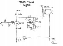
1) No need to call it an RH84 Redux - there are more parts involved in making this one than the original RH84 or the RH84 rev2. You should call it COMPLEX, since it is more complex.
Maybe I am an outsider and do not know what Redux stands for? Anyway, reduced it is not, rather more complicated.
2) This is not an RH amplifier, and should not be compared to one unless the idea was to compare some EL84 amp with the RH84. The Rfb of 100k is not performing the same task, or not performing to the same extent. That is why you need some additional global NFB. The RH84 does not need additional NFB, neither in the form of global, nor in the form of ultralinear taps.
3) If you really meant for your amp to be easily reproduce-able you should have provided some schematics for the CCS, not just put in "5mA CCS" as if you were going to sell (no pun intended) some CCS "a la Bottlehead" (buy the part, in other words).
4) The input cap is superfluous and together with the grid resistor of the driver tube forms an RC filter limiting the frequency response (68nF and 150k).
I find it interesting how you have drawn your schematics by hand. I assume that you are not using any software to draw schematics and perform simulations...
While I do not have a spice model for the 6gk5, the tube seems fit for the driver task in the RH84 - high transconductance and high mu. It might or might not work a little better than the ECC81, but it is less common. Maybe in the USA you can easily get them, but I have none and I think they are fairly rare in Europe.
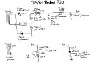
I have thus simulated your Redux version, with ECC81 as driver, and without the additional global NFB. I am not sure of the B+ you intended, but I assume it would have been 300V. Also, to avoid complication, the g2 has a separate power supply which approximates fairly your VR regulation arrangement.

The general operation of your Redux can be seen from the attachment. I believe the global NFB would have helped somehow, but the amplifier has already clipped at the output power illustrated.
I cannot simulate the gNFB since I do not have a good output transformer model, but at this point think it is of little relevance. While gNFB would have lowered distortion and input sensitivity, the amp would nevertheless have clipped at more or less the same output power.
Also attached is the RH84 rev2 simulation. I believe it speaks for itself, take a good look at all the details illustrated. More power, less distortion.

On one hand, it might be objected that the 6GK5 might be a more capable tube than the ECC81 - but in all fairness, the difference would not have been that huge. After all, the 6GK5 would draw the same current the ECC81 draws here, since it is defined by the CCS and the LED bias. Using the same model is actually more fair, particularly since this is not a comparison of 6GK5 vs. ECC81, but two design concepts.
And, the first documented example shown here. Of course, if someone would like to reproduce the same simulation in some other software with other models, this would be a welcome contribution.
An externally hosted image should be here but it was not working when we last tested it.
Cool, I like your illustration very much!
Maybe it was long due?
As for truth, in academic circles it is usually established by proof, not by word of mouth. While DIY is certainly not academic, it relies on academic sources - the guys who invented all the stuff we use (tubes, transformers, diodes...) were not quacks!
The truth might be painful to some.
When you find the truth let us know Alex !
Shoog
Just the opposite - it is you guys who are not providing "academic" evidence for your claims.
Build an RH amp, subject it to tests, and let us know how it fares (with truthfulness and open mind, of course). If you are not into building and do not own equipment such as FFT analyzers, just simulate.
I hope mentioning the word "academic" is not offensive and can be considered as a personal attack on educationally challenged individuals, to whom I sincerely apologize if that is the case.
In academic circles, you need to present and publish works if you want to advance towards Master and Doctorate (PhD) titles. Said works have to be corroborated with statistical and other evidence that the conclusions presented are correct. The publications as well have to adhere to a certain level of standards.
That is in stark contrast with the way many DIY forum contributors act - claims without substance, corroborated by stories confirmed by the stories of others. There is nothing wrong with that, since this is not an academic ambient, unless subjective reasons are the cause of denigration (rubbish design, stinky, "not understanding the basics", guitar practice amplifier... to mention but a few words uttered in this thread alone).
Haters are going to hate, aren't they?
I haven't ever seen any real data on the RH-- stuff before (just sims), but a search found this:
http://www.diyaudio.com/forums/tubes-valves/236769-why-use-pentode-5.html#post3512545
On this never ending debate about the triode versus pentode input tube driving the shunt feedback load:
It seems to me that if one did an apples to apples comparison of two tubes (triode vs pentode) with the same nominal gm and same (unbypassed) cathode resistor, for the same voltage output swing into the same resistive load (so identical currents), that the triode must be a little more linear (but would require more input signal to overcome the internal plate feedback). Reason being that the pentode's fixed screen V is equivalent to a triode with a frozen plate V. While the triode here, in this case, is providing some limited linearizing internal neg. feedback from its limited (due to shunt loading) plate voltage swing.
The reason one might still prefer a pentode, is that the pentode's fixed screen V will typically allow for higher gm development than the triode can develop at its minimum plate V swing. So then (with more gm available) one can use a higher cathode R with the pentode to linearize further beyond what available triodes could offer.
But then the data suggests that the input tube here is intentionally providing distortion cancellation (mainly 2nd H). So it is not even a question of minimal distortion from the input tube, but simply of "tuning" it for best overall cancellation. Usually this technique makes higher harmonics worse though.
The choice of the 12AT7 for the input tube may be opportune here though. Looking at its gm versus current curves, the 12AT7 gm vs current are almost linear ramps, which would be characteristic of a square law device (rather than a typical 3/2 power law tube). This is desired for mixer tubes (and 12AT7 is listed for mixer use) since 2nd order products would be enhanced. So in this case, mainly 2nd harmonic distortion is produced under the heavy plate loading. So higher harmonic generation may be somewhat muted here, but not zero.
Last edited:
1) This is a nice story, but besides confirming in the end that you have solved the problem with negative feedback, you have not produced any evidence in the form of screenshots or links to screenshots, etc. It remains thus unsubstantiated, although there is no reason not to believe that there have been high order harmonics in that push-pull design.
I did the design and testing on the Vixen during the summer of 2005. Unfortunately for me my crystal ball was hazy that day and therefore I didn't realize I needed to take screen shots because they would be requested in eight years. Sorry 'bout that. If my word isn't good enough... well, then tell me why I did not claim absolute perfection to make myself look like the Master Amp Designer of All Time?
2) If you have solved the problem with an effective amount of gNFB, why would an adequate amount of local NFB (anode to anode) not be able to solve this or similar problems? After all, local NFB does not include the output transformer into the loop and is therefore less prone to oscillation... etc.
You answered your own question here. There is no difference between local NFB and gNFB so far as the output characteristic is concerned. Linearizing a non-linear type like the 807 requires more NFB. If you break it into 7.0dbv of local, and 6.0dbv of global, it's still the same 13dbv overall, but less chance for instability because not all of it includes the OPT with its squirrelly phase behaviours at either end of the audio band.
1) As far as I can see, again similar output stage, push pull, etc. as above. Again without any "evidence" besides your interesting story.
My crystal ball was in the shop for repairs that day when I did this design in 2007.
Can you produce some links to some reputable source that states IT MUST BE DONE, OTHERWISE... ?
I am that reputable source, that's the way I design with pents. Do it however you please, but don't expect me to buy one.
Back in the days, as you say, if you were to tackle the issue flawlessly, you would have had a separate power supply for g2 - just take a look at the above linked STC datasheet.
A difference without a distinction.
Furthermore, Ultralinear was not "invented" back in the days, but slightly later - whichever came first, Ultralinear bears a potential problem of higher g2 potential than anode potential, which might or might not cause problems, depending on the tube, etc. Neither flawless nor universally applicable, and requiring an additional tap... and the percentage of windings (and subsequent feedback arrangement between anode and greed) also remains a disputed issue.
Yes, it was, and by Alan Blumlein in the 1940s, H & K get credit for the name "Ultralinear", but not the idea.
Probably because you are so lucky to have been born and live in the US of A where, among other things, hamfests exists and people can meet and swap.
VR tubes can of course be ordered from sellers on the net, but all that I have already wrote on the argument remains:
1) You need the tube (tubes),
2) You need the socket (sockets),
3) You need the place for those tubes and sockets,
4) You might not be able to source them (tubes and sockets), you might not have the place where to put them (small amp chassis, many build RH amps without a rectifier because they do not have one, or because it takes up space... let alone VR tubes).
That said, I like the glow of VR tubes and intend to experiment with them because they look better than zeners and I happen to own a few.
And I will not reply to this subject, as well.
You can say the same for all VTs. The problem is even worse when it comes to solid state. Devices change frequently. Just try to find lateral MOSFETs. These are the "Western Electric 300Bs" of the SS world: rare to find genuine ones, and when you do, you'll really pay for them. Genuine VFETs? Like genuine 45's -- rarely ever seen anymore (and I think you'll have better luck with the 45s)
This is not actually true. Active regulators have a different output than unregulated (choke first, for example) power supplies.
Yes, they do: much better regulation under load, and much less noise.
While most SS regulators are much more effective in filtering the ripple, and stabilizing the voltage, they have an inherent noise, which mostly originates from the voltage reference. The better the voltage reference, the less noise. Of course, active elements also produce "noise". Whether you hear this noise or not (being able to hear, being disturbed by it, etc.) is a different issue, but the noise of regulators is widely documented on the net.
Really? And you were the one demanding links of me? Hypocrite.
This personal attacks story is unbelieveable stuff. It must be down to cultural differences. It seems that in the US of A and other Anglo-Saxon countries it is permitted to some people to speak in denigration of the work of others (using words such as rubbish, stinky...
I used no such words and you damn well know it. You have, and you continue to, attack me personally by stating and implying that I am incompetent.
...assuming that an amplifier which is meant for music listening is eventually good as an instrument amplifier, and a practice one at that, whish in itself is meant to represent an offence, while in fact that the requirements for those two types of amplifiers are different, etc.) while others are considered as performing a personal attack if they remind them that their language is not adequate, that their claims are unsubstantiated, and that they are offending others by making such statements.
Judging on technical merits, and I find the design lacking for the reasons I and others already stated. You sign up here for no other purpose than to attack, call us incompetent, etc, etc, etc.
It would be misspelled if it was the star... you seem to know quite little of marketing, politics? (or is this now a personal attack, while assuming a misspelling is not?)
I know plenty about marketing. It's obvious you don't know what smilies are meant to convey.
OK, one more time: I do not have time for empty talk. I will not reply to unsubstantiated stories. Please produce adequate evidence of some sort if you intend to continue.
Yeah, we can all see how little time you have for empty talk. What was your join date again? Your post count?
Alex please refer to smoking amps post regarding tests on your designs. Similar tests by other members on this board have produced similarly poor results in the past - that is more than enough for me. It goes into some considerable detail as to why reliance on computer modelling is inadequate to assess the results of your design as it beomes very tube dependent and this is not captured in models.
If I thought that you were a trained Electronics Engineer I might take your comments more seriously, fortunately there are other people here who show a sound grasp of engineering.
Remember I built an RH807 and decomissioned it.
Shoog
If I thought that you were a trained Electronics Engineer I might take your comments more seriously, fortunately there are other people here who show a sound grasp of engineering.
Remember I built an RH807 and decomissioned it.
Shoog
Last edited:
- Status
- This old topic is closed. If you want to reopen this topic, contact a moderator using the "Report Post" button.
- Home
- Amplifiers
- Tubes / Valves
- RH 84 Variation: Direct Coupled Pentode