Is anyone here familiar with the model 9? I know its rare and old and has enormous cache' But is it as good an amp as the price it fetches? My first from scratch amp was an 8b and I loved its sound but it wasn't quite powerful enough for my Snells. I really like the EL34 mid-range especially. The OPT's would be a real problem. So can anyone recommend a better PPP EL34 schematic?
Well I just found the answer to the above question. In a similar thread Sy and KevinKR gave the 9 some really high praise. So now the other question. How do I come up with output transformers? I have only minimal data on the. I want to build a stripped down version. Just the basic audio section with none of the fiddling knobs. Anyone have transformer data?
The original design of the Marantz 9 transformers is a lost black art. Having been there and done that many years ago I came up with an output transformer that would work with the Matantz 9 EL34s and some others as well. I was lucky enough to get a pair of experimental transformers built through a friend's father that was VP of Executone in NY. This transformer worked very well and I still have the pair. The only change I would make today on this design would be to deduct one turn from the 16 ohm secondary winding. This would make the 0-4-16 ohm truely balanced for balanced cathode feedback should I choose to use it that way. The only spec that could not be met was the 95% efficiency rating. This design is from 1967 and the builder is probably long gone.Anyone have transformer data?
Attachments
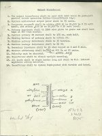
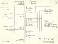
A truthful answer is I don't know. They were not meant to be a clone of Marantz 9 OPTs. Only to be an acceptable impedance and power match for PPP EL34s. I don't know what the screen tap percentage of the 9 was. And the transit response is probably different and would need squarewave tweaking. There is also the dampening circuit on the secondary which seems to entail some extra windings. But it would certainly work on a generalized copy.With these transformers can I build the original circuit without modification?
To put my comments into perspective:
1. The 9 was one of the best amps of its era.
2. It incorporated several elements that were ahead of its time. The schematic is an educational experience.
3. It was not designed, it was engineered. That's exceedingly rare in high end audio today (see the thread about the stunningly expensive Japanese phono stages with lots of non-functional parts).
4. One can do a better circuit today. The price it now fetches is a function of collector value, not intrinsic performance in 2012 terms.
5. If you want to clone it, you have no chance of exactly duplicating the output transformer, though better ones can be built.
6. Give #5, you will without question have to redo all of the compensation and feedback, as well as the little tricks peculiar to the original layout (e.g., the plate inductors in the output stage), in order to accommodate the new transformer and layout.
HollowState, did you build an amp with those transformers? If you did what circuit did you use?
Quinnling, I've spoken to Kevin Hayes at VAC a few times. They have many parts available from the reissue but not transformers. The company they commissioned for the OPT's doesn't build transformers. He wouldn't give me their name. He did, however send me to Doc Hoyer, who said he could build me a set. But his pair would require a second mortgage. Doc did tell me that Saul was obsessed with high frequency ringing and that was the purpose of the tertiary windings.
Sy, After I built my 8b clone I fell in love with the EL34. For that amp I used ST70 OPT's.
An acquaintance who once owned an 8b listened to it and said it was very similar to an original 8b sonically. And lastly, If there are better circuits today could you point them out? A simpler circuit that has a dedicated transformer would be helpful.
Thanks everyone, kevin
Last edited:
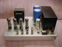
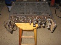
Actually I made two sets of amplifiers with these transformers. The first was a modified copy of a Heath W6M using KT-88s or 6550s. Kept and used those for years. Then I made one that used four EL34s. I do not have a drawing because the circuit was in my head. But I will describe it.HollowState, did you build an amp with those transformers? If you did what circuit did you use?
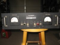
The input is a modified cross-coupled phase inverter with a transistor in each cathode of the first tube. (5687 & 5965 or 12AU7A) The plates of which are direct coupled to an elevated differential amplifier. (6CG7 with sections paralleled) Their plates are capacitor coupled to the output tube grids with individual bias adjustments. (behind each tube) Tube current can be read across 10 ohm cathode resistors with the small 1ma meter. Inverter tubes are DC filaments. And a single overall feedback from the output secondary to the lower inverter grid.
The big black box on the right side is a hermetically sealed multiple transformer package salvaged from a Lambda C281 or 481 (I forget) tube power supply like the kind seen below. Inside is a plate transformer, a multi winding B+ and filament trans, and a choke. I still have a pile of the these supplies stacked up in the garage. They used to be easy to get at hamfests or government sales in the 70's.
Attachments
- Status
- This old topic is closed. If you want to reopen this topic, contact a moderator using the "Report Post" button.
- Home
- Amplifiers
- Tubes / Valves
- marantz model 9