
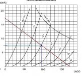
The voltage at the cathode -2V.What is the voltage (min and max) that it will see?
The voltage at the cathode -2V.
Attachments
Last edited:
You could also use a 267R resistor...tubes tend to self regulate their bias point.
I know...OLD SCHOOL
")
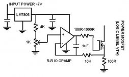
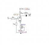
I agree, but I want this to rid with electronic circuit with mosfet with a constant current of about 7.5mA.
thank you and cheers!

Attachments
Last edited:
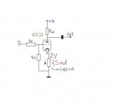
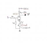
Here's the complit schematic!I agree, but I want this to rid with electronic circuit with mosfet with a constant current of about 7.5mA.
thank you and cheers!
Attachments
It makes much more sense to put the CCS in the plate circuit. (You'll get good linearity and gain approximating mu if the AC load impedance is high relative to rp.)
Placing an unbypassed CCS in the cathode circuit will result in much less than unity gain in a common cathode amplifier.
There is a voltage compliance issue as well, there are no commonly available CCS that perform well with just 2V across them. (incidentally +2V at cathode)
Depending on required gain you might want to consider a single red led for cathode bias and a CCS for plate load.
It makes much more sense to put the CCS in the plate circuit. (You'll get good linearity and gain approximating mu if the AC load impedance is high relative to rp.)
Placing an unbypassed CCS in the cathode circuit will result in much less than unity gain in a common cathode amplifier.
There is a voltage compliance issue as well, there are no commonly available CCS that perform well with just 2V across them. (incidentally +2V at cathode)
Depending on required gain you might want to consider a single red led for cathode bias and a CCS for plate load.
1. Gost22 wants to regulate current. Placing a CCS in the plate circuit is for a different purpose. The load line would be almost horizontal. Perhaps something to look at. (If you can get a very low capacitance CCS)
2. Yes, you are correct in that a CCS without a bypass cap will get zero gain to the plate.
Gost22, you do need to put a bypass cap in the cathode cct. (parallel with the CCS)
3. The CCS I have suggested will go down to almost 1V...Well within what Gost22 asked for.
4. The bias point is specified at 7.5mA not 2V. Depending on the tube it might be 1.9V or 2.1V but the CCS will compensate for that. LED would not. LED's also have temperature characteristics that are rather bad for a voltage reference.
Just to see if I can find a solution to the problem, without trying to justifying it.
Problem to solve : low noise CCS 7.5mA at 2V headroom.
Proposed solution :
5x heavily-degenerated 2SK246BL with matched Idss in parallel,
and 1x 100~125R common source resistor (for all 4 FETs) to generate the negative Vgs as required.
Adjust resistor value to achieve 7.5mA.
Should be lower noise also than a BS170, and without the added complication of an opamp-based circuit.
Patrick
Attachments
What post #9 says. LED in the cathode is all good.
See the 6SN7 stage in the attached schematic.
Do you have a drawing of or can you describe the CCS you used for the 6SN7? I didn't see it on the drawing.
My new years resolution is to build a 6SN7 stage with a horizontal load line to drive an 845 transmitter triode. I have some DN2540s on order now but am still reading up on the subject and am interested in other schemes.
Last edited:
Take a look at SY's "His Master's Voice" article for a good example of the cascode CCS I am thinking of: http://www.diyaudio.com/forums/diya...oise-thoroughly-modern-tube-phono-preamp.html
- Status
- This old topic is closed. If you want to reopen this topic, contact a moderator using the "Report Post" button.
- Home
- Amplifiers
- Tubes / Valves
- Circuit or schematic for current source of 7.5mA