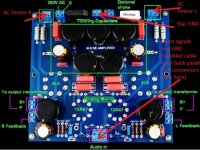
I'm trying to attach some pictures. The circuit is realized on PCB - see the first page with link to supplier's web page.
All pictures show top plate of amp with output transformers open but there is not difference in 100 Hz hum if the top plate is open or closed.
I have a couple of questions, Vcelkamaja:
1) Are the PCB standoffs completely isolated from the PCB ground plane(s)? They should be - it's hard to tell looking at the photos and the website doesn't provide the PCB layer stackup. Easy to check with an ohmmeter with the PCB out of the box - each of the standoff vias should be isolated, connected to nothing. If they're connected to the PCB ground, then you will probably should use non-conductive standoffs (unless you already are using them...)
Also make sure that your mounting hardware have not broken through the soldermask and are touching a ground-plane on the PCB. It happens, soldermask is quite brittle and sometimes a washer can poke through and make contact. Check both sides - make sure there is no outer-layer copper plane that is under your mounting hardware. Use insulated washers if necessary or, better, hardware that does not rest on top of any outer-copper layer on either side of the PCB.
The PCB photos on the mfgr website have shadowing that might be copper-planes which appear to be very close to the mounting holes - it's impossible to tell from the photos, but hardware breaking through and touching outer ground-plane layers is something that's burned me in the past so I'm sensitive to mounting hardware issues...
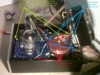
2) What are the two black wires that are taped to the board with blue tape? Looks like they come from the power transformer area and are soldered somewhere in the preamp area. I couldn't tell where they're connected from your photos - the preamp tubes shadow the area.
Good luck - hope you have the amp humless soon!
~ RF Dude
Last edited:
There are two really-easy ways to get hum into the input, which is probably the worst place to have it, since it would then get amplified.
1. SURELY your input signal grounds closely follow the input signal conductors ALL the way to the grid-to-ground input resistors (e.g. R6), and they are tightly twisted ALL the way from the jack to the input resistor. (You should NOT take the input ground from the jack directly to the star ground!) The schematic is very misleading. The input ground should show two wires from the jack, one following each input signal to its grid-to-ground resistor.
If not paired closely that way, then they are big loop antennas for time-varying magnetic fields, such as AC and rectified AC. See "Faraday's Law" (or Maxwell's Equations).
2. Also, the ground ends of the grid input resistors should have their own separate conductors, all the way back to the star ground, shared with nothing else from the circuit. Again, the schematic is very misleading, showing many connections to a single ground symbol, which includes the input resistors' reference-ground points!
Otherwise, any large OR fast-changing currents, from other parts of the circuit, that share the ground conductor, will induce voltages across the ground-return conductor's inductance (and resistance). And those time-varying voltages will then appear back at the non-star-ground end of everything that shares that conductor. If the ground end of the grid-to-ground input resistor (i.e. the amplifier input's ground reference voltage) has a time-varying (bouncing) "ground" voltage, that voltage will be arithmetically summed with the input signal! That would be "a BAD thing".
-----------------
As always, keep all AC and rectified AC conductors and components, and all high-current and fast-changing current conductors and components, as far away as possible from, and orthogonal to, all small-signal and "quiet ground" conductors and components.
Also, as DF96 mentioned, check to see whether or not the star ground point is DOWNSTREAM from the last PSU reservoir capacitor. If it is NOT, then it must be moved so that it is. Otherwise it will be sharing a conductor with part of the charging-pulse loop, which would basically be guaranteed to produce hum.
Last edited:
rfengineer2013: The PCB is isolated from the chasiss and there is now connection realized by the standoffs. I have checked it with ohmemeter. The only connection is with the single wire from star GND to chassis. If I disconnect this wire the PCB GNS is isolated from the chassis.
As for the wires the black wires you've mentioned are the wires feeding input signal from the jacks to input terminal on the PCB. They are shielded.
As for the wires the black wires you've mentioned are the wires feeding input signal from the jacks to input terminal on the PCB. They are shielded.
Attachments
gootee: You are right but I believe that if I shorten the grid of lower input tube to GND right at the tube socket and there was no improvement in 100 Hz hum the issue is not the input wires or ground. Or?
A few imporant observations I made yesterday are:
- if I unplug input tube from the socket there is no hum --> output tubes, transformers couplings and output grounds are ok
- if I shorten input to GND or even input tube grid to GND the hum is still there --> input wires and GND is probably ok
- the hum appears ~ 10 seconds after power on - it is quiet after power on and ramping up during ~ 10 seconds, then it is stable. It disappears immedaitely after power off
The only thing that I can try now is to increasing filtering capacitor for input tube. Otherwise I don't know what else to do.
Hi!
Your hum is caused somewhere around the input tube. So lets look there.
One point which is not clear yet from your description is the ground connection of the chassis. It seems that the transformer shield is grounded. Is it connected to safety earth only or also to signal ground? Is there a connection from the rest of the chassis to signal ground? Verify the connection with a DVM.
Another strange thing: There seem to be separate heaters for the upper triodes in the SRPP. This is a good thing since this enables the elevating of the heaters of the upper triodes. But the schematic indicates that both are at ground potential. In that case the heater to cathode voltage of the upper triodes would be exceeded. This could cause the tube to develop heater to cathode leakage which can introduce hum. Can you clarify the heater arrangement?
Are the two triodes at the bottom of the SRPP stack in one bottle and the upper ones in another? Or are the tubes separated left and right channel?
Do the out tubes share a heater winding with the input tubes?
Best regards
Thomas
rfengineer2013: The PCB is isolated from the chasiss and there is now connection realized by the standoffs. I have checked it with ohmemeter. The only connection is with the single wire from star GND to chassis. If I disconnect this wire the PCB GNS is isolated from the chassis.
As for the wires the black wires you've mentioned are the wires feeding input signal from the jacks to input terminal on the PCB. They are shielded.
OK, very good. Now I understand a bit more.
Are you running shielded twisted pair or coax? And how is the shield terminated - at both ends or just at the input connector?
Hi rfengineer,
there is no point in checking the connection to the input tube, since grounding the grid right at the tube sockets makes no difference. The hum is introduced somewhere else.
From the description here I see that the chassis is conencted to ground, so thats ok.
Lets clarify the heater arrangement that is still not clear.
And do the test with increasing the filter cap of the driver stage and see if it changes anything
Best regards
Thomas
Thanks Thomas. Not trying to increase the noise level...
You might be on to something with the elevated cathode potential. The board photo on the Analogmetric website clearly shows pins 2 and 6 of T2 connected together - which implies the upper and lower triodes are indeed in the same tube.
You might be on to something with the elevated cathode potential. The board photo on the Analogmetric website clearly shows pins 2 and 6 of T2 connected together - which implies the upper and lower triodes are indeed in the same tube.
I don't think the OP has operated the heaters from an isolated DC source as yet. It is a quick easy way to help eliminate one source of noise. I use 12V 7Ah battery, which can go through a 5V regulator with a couple of diodes in the 0V leg toget to 6V. I've also used a 6V lantern battery.
And the last time I checked, Thomas, the 12AX7 used a center-connected filament for both triodes ")
The upper cathode is running at about 155V, and with the filament way down at 6.3VAC seems like a good opportunity for mischief.
Yes, the battery idea has great merit! I think Thomas might have suggested it earlier, or on his blog, and I will certainly 3rd the motion!
The upper cathode is running at about 155V, and with the filament way down at 6.3VAC seems like a good opportunity for mischief.
Yes, the battery idea has great merit! I think Thomas might have suggested it earlier, or on his blog, and I will certainly 3rd the motion!
Last edited:
Thanks for all your comments. Regarding heaters:
- there are separate heater voltages for left and right channel (separate transformer windings)
- input and output tubes share heater voltage
- heater volatges are AC and there is a CT resistor networ grounded in the middle
One thinkg I tried as well was that I doscinnected AC heater volateg from one channel while keeping B+ voltage connected and this channel was without hum. Does this mean that there is something wrong with heaters?
So if I understand correctly the 3 things to try now to identify hum in input triode are:
1. increasing filtering capacitor to input tube
2. elevate CT resistors in heaters - remove the center tap from GND and put it onto cathode?
3. replace AC heating voltage with 6 V battery or DC power supply
Right?
1. increasing filtering capacitor to input tube
2. elevate CT resistors in heaters - remove the center tap from GND and put it onto cathode?
3. replace AC heating voltage with 6 V battery or DC power supply
Right?
Hi!
Yes worth trying, although I think the üproblem has to do with the heaters, so maybe try this first:
Yes, apply a voltage divider from B+ which will put that node to maybe 60-70V positive. Important: Decouple that node AC wise, that means put a cap from there to ground, maybe 47uF. Don't make teh voltage divider too high impedance. Keep the resistance of the lower resistor in the voltage divider under 20k.
Even if that doesn't solve the hum problem, it is more healthy for your tubes and should be done anyways
This is a recommendation which is often given in case of hum issues. A power amp should be hum free with AC heaters. I would only see this as a last resort if nothing else help
Best regards
Thomas
1. increasing filtering capacitor to input tube
Yes worth trying, although I think the üproblem has to do with the heaters, so maybe try this first:
2. elevate CT resistors in heaters - remove the center tap from GND and put it onto cathode?
Yes, apply a voltage divider from B+ which will put that node to maybe 60-70V positive. Important: Decouple that node AC wise, that means put a cap from there to ground, maybe 47uF. Don't make teh voltage divider too high impedance. Keep the resistance of the lower resistor in the voltage divider under 20k.
Even if that doesn't solve the hum problem, it is more healthy for your tubes and should be done anyways
3. replace AC heating voltage with 6 V battery or DC power supply
This is a recommendation which is often given in case of hum issues. A power amp should be hum free with AC heaters. I would only see this as a last resort if nothing else help
Best regards
Thomas
My understanding is that you have been saying all along that this is 100Hz hum, which means PSU. If it is actually 50Hz hum then heaters are the likely source. It is difficult to provide hum-free AC heaters on a PCB, as the required conductor twisting would need a multi-layer board with lots of high current vias. Better to take the heaters off the PCB and use twisted wire instead. Or use DC. Bear in mind that lots of people have trouble when they first adopt DC heaters, as you need much thicker heater secondaries: for every W of heater you need about 3VA for unstabilised, and maybe 4VA for stabilised.
<snipped>
- if I shorten input to GND or even input tube grid to GND the hum is still there --> input wires and GND is probably ok
- the hum appears ~ 10 seconds after power on - it is quiet after power on and ramping up during ~ 10 seconds, then it is stable. It disappears immedaitely after power off
<snipped>
NO.
If shorting the input does NOT take away the hum or buzz, then that means that it COULD BE caused by an "enclosed loop area" antenna formed between the input signal and signal ground paths. (Shorting the input leaves the loop remaining intact, so that current can still be induced in it by the time-varying fields.)
What is the difference in the loudness of the hum, when you SHORT the inputs and when you OPEN the inputs?
------------------
Actually, either way, it MAKES NO SENSE to NOT keep the input signal and the input signal ground reference conductors together, all the way to the input resistors. You are just ASKING for every bit of interference and RF and EMI that you can possibly get, the way you have it now.
Without first ensuring that you have properly twisted (or twisted and shielded) input pairs, and properly star grounding the most sensitive single points in your system (the input tubes' input ground references), there is no point in even looking or discussing further.
You would NEVER want to leave those two conditions uncorrected, anyway.
And you cannot perform sufficient testing to rule them out.
So why do you resist? (Are we enjoying the armchair troubleshooting so much that we just don't want it to be over yet?)
And I have seen many cases of hum or buzz that were fixed by correcting one or both of those conditions.
-----------
What would be easier, at the moment, and could be very helpful, would be more PHOTOS of the details of the WIRING and the pcb.
Also, exactly where is your star ground, relative to the smoothing caps' grounds?
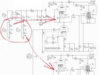
gootee: I don't resist I'm just not sure what to improve. I believe that I don't have any ground loops. As for the input - there are inpit jacks on the back panel (isolated) with shielded coaxial cable feeding both GND and signal wire to input terminal. Here the GNDs for L and R channel are connected together and to PCB. Please check attached photo. Is there anything wrong with it?
As for the star GND it is shown on the photo as well and it is close to filter capacitors. All the wires from output transformers and outpu terminals goes to this point (not the input GND that is connected on the other side of the PCB to input terminal). Star GND is connected to chassis with a single wire as well PE from mains and trnasformer shielding is connected to this single point on chassis.
If I shorten the input RCA jack, input terminal or grid of input triode to GND it is always the same. I mean the audible hum level is not changed.
I'm just not sure what to improve. I believe that I don't have any ground loops. As for the input - there are inpit jacks on the back panel (isolated) with shielded coaxial cable feeding both GND and signal wire to input terminal. Here the GNDs for L and R channel are connected together and to PCB. Please check attached photo. Is there anything wrong with it?As for the star GND it is shown on the photo as well and it is close to filter capacitors. All the wires from output transformers and outpu terminals goes to this point (not the input GND that is connected on the other side of the PCB to input terminal). Star GND is connected to chassis with a single wire as well PE from mains and trnasformer shielding is connected to this single point on chassis.
If I shorten the input RCA jack, input terminal or grid of input triode to GND it is always the same. I mean the audible hum level is not changed.
Attachments
Last edited:
- Status
- This old topic is closed. If you want to reopen this topic, contact a moderator using the "Report Post" button.
- Home
- Amplifiers
- Tubes / Valves
- Hum in tube amp