+1 ,make it 12 pages
Mona

The amp is virtually empty on the downside, nothing important, only filament diodes, capacitors and regulators.
There exists no special circuit diagram, just self-biasing scheme for all tubes. Just a grid resistor, a transformer, a cathode resistor and a cathode bypass capacitor!
First of all, great work, Petavgeris! Exotic to the max.
Any tips on working with ultra-HEAVY amplifiers? I'm currently building one that should be just under 100kg and am wondering how best to deal with that weight while finishing up the build - of course, I'm leaving the heaviest pieces to last so I don't have to lift them every time I flip the amp, but perhaps you have some other insights for us?
Hello Magz!
Sorry for my late response, I overlooked your posting.
It is not possible to flip those amps just as they are. You need two heavy blocks, one per side, having enough space in between. The amp must be placed at around 70-100cm from floor in order to work under the chassis. Two strong persons to flip the chassis. This chassis is very well engineered and there exists not a chance of bending or damage due to excessive weight.
Hope all this helps a bit!
Peter
Ha! For all we know it's just a bunch of iron on a white chassis and doesn't even work. I suggest we all start referring to it as "The Emperor's New Amp" until he posts a schematic.
The amp is virtually empty on the downside, nothing important, only filament diodes, capacitors and regulators.
There exists no special circuit diagram, just self-biasing scheme for all tubes. Just a grid resistor, a transformer, a cathode resistor and a cathode bypass capacitor!
I'm still pretty new to this forum and even tube amps in general but so far I've designed two unique tube amps on my own.
I don't see what gives you others the right to demand a schematic for something he made. It's his choice, just like its my choice to release my designs (which I do release freely by the way).
All I'm saying is that I don't think its right to keep blasting him with all of your greedy schematic comments.
Do what you want, this is just my
PS: I love this amp, absolute work of art. I'm not into all of those people that make amps and what not with chassis made out of slabs of copper and then talk about how heavy it is etc, this is true beauty. Nice pure white chassis, full of complexity, and I really LOVE how you've arranged those MV rectifiers to be a bridge rectifier.
Keep up the good work!
Last edited:
Hi guys!
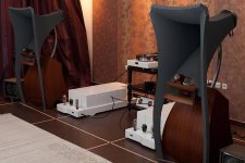
As I promised you a few days ago, I will post some pictures of the project I'm now finishing. It is an exotic power amplifier equipped with 211 power tube.
Due to the unique specs, I would say that I'm quite certain that this might well be one of the most exotic amplifiers ever made. There will be several posts regarding the specifications afterwards[/SIZE][/B], for the time being I have uploaded some pictures of this unique project.[/SIZE][/SIZE]
It is a 35 W/ch Class A2 power amplifier around 211 output tube, with 300B driver tube and EML20A input tube. There are totally 15 iron pieces spread allover, all of them in double c core configuration. Signal path is 8 cm from input socket to 1st tube grid and around 20cm of copper leads coming out of the OPT secondary, directly soldered onto the loudspeaker connectors.
For the time being enjoy the pictures.
I don't think it's unreasonable to expect something approaching detailed specs etc. nearly a year after they were promised by the OP....up to this point it's been a whole lot of navel gazing going on and narratives about the herculean doses of courage, $$$$ and dedication required to complete this project.
It is impressive looking...but that's all we can infer from the pics and hyperbole thus far...a portrait of excess IMO...not intended for the proletariat and certainly not for anyone who might ask how it's constructed, or how it works or, gawd forbid, schematics...
Ha! For all we know it's just a bunch of iron on a white chassis and doesn't even work. I suggest we all start referring to it as "The Emperor's New Amp" until he posts a schematic.
Unbelievable how you react without any respect....
 .
.As far as I read the thread I can see that almost all the curiuos questions get an answer and the only thing he clearly wants to keep to himself is a schematic...so what !!!!!
I can imagine that maybe your lack of experience may give you the idea that the amp does not work....but anyone with a bit of basic technical understanding and an empathic feeling will not doubt that ...so you might want to erase the word "we" in your opening sentence....
I reckon that nobody wants to post in a hostile environment....so your answer does not help to get further pics or/and info....
I don't see what gives you others the right to demand a schematic for something he made. It's his choice, just like its my choice to release my designs (which I do release freely by the way).
All I'm saying is that I don't think its right to keep blasting him with all of your greedy schematic comments.
Do what you want, this is just my
PS: I love this amp, absolute work of art. I'm not into all of those people that make amps and what not with chassis made out of slabs of copper and then talk about how heavy it is etc, this is true beauty. Nice pure white chassis, full of complexity, and I really LOVE how you've arranged those MV rectifiers to be a bridge rectifier.
Keep up the good work!
Hello 'TheTubeAmper'.
Thank you for your kind words.
I do not have any sort of problem releasing the schematics. Actually I have done so through my writings...
Those guys that are still complaining, judging from their writings are totally unaware of tube amp design. The reason is that I have thoroughly explained everything related to the power supplies, tubes operation, biasing, etc. As soon as they are still asking questions, there is no room for me to respond. They are not up to the level even to understand the basics, so I have nothing more to write. Let's say I'm just enjoying their ignorance.
Now, regarding how I am winding the transformers, how many Henries is each of the interstage trafos, how many turns per primary or secondary coil, magnet wires diameter, winding scheme, how I succeeded in maintaining a perfectly linear load from subsonics to ultrasonics, what the exotic cores are made of, where do I place the custom order to manufacture all this hell of c cores, sorry but I have the right to keep this info undisclosed.
All other questions have been asked so far.
Finally, those MV rectifiers are the best ever manufactured, at least for this position. I have evaluated every and each crazy MV rectifier existed, this is an outperformer. Those 4 MV tubes do not form a bridge, like in Kondo designs. They compose two separate power supplies, two for 211 rectification and two for 20A & 300B rectification. In all my designs of power amps (otherwise IMHO a creation cannot be justified as 'exotic'), I always use a dedicated power supply for the output stage. This stage must be kept completely isolated from everything else, this is where my experience leads to.
Thanks a lot for your kind remarks.
Peter
Peter, my offer to dispose of any of your amplifiers still stands -- just send them to me.
This is the kindest remark of all!
Thank you!
Hi Peter,
thanks for showing us your beautyfull amp.
" In all my designs of power amps (otherwise IMHO a creation cannot be justified as 'exotic'), I always use a dedicated power supply for the output stage. This stage must be kept completely isolated from everything else, this is where my experience leads to."
This is 100% true.
I´m always use sep. powersupps for each stage. Sound is so much cleaner when you do so.
Keep on your nice work,
Hilmar
Hi Peter,
thanks for showing us your beautyfull amp.
" In all my designs of power amps (otherwise IMHO a creation cannot be justified as 'exotic'), I always use a dedicated power supply for the output stage. This stage must be kept completely isolated from everything else, this is where my experience leads to."
This is 100% true.
I´m always use sep. powersupps for each stage. Sound is so much cleaner when you do so.
Keep on your nice work,
Hilmar
Hilmar,
thnak you for sharing your experience.
We seem to be right. It is mandatory to use 100% separate and 100% isolated power supply for the output stage. Sound is much more clear, immediate, crispy, glossy, everything is miles better.
Try to compromise there and you have downgraded your amp right before you begin!
Remarkable work. I doubt very much that anyone would go to such lengths to produce something just for a few photos and the admiration of a few strangers. The choice not to provide schematics or some numbers and pictures of an ocsilloscope taking measurements(all of which prove nothing) is not a valid reason to jump all over someone. judging by the rest of the equipment shown along side of the amps I personally find no reason to doubt that they are for real.
Congrats. I can only dream of such extravagance.
Congrats. I can only dream of such extravagance.
Yes Peter,
we are right
I use 2x 866A for the endstage with 10H/10µ/10H/100µ the chokes with low resistance (30Ohms) and all the caps are MPs (Bosch or Siemens).
For the prestage i use a 83 MV followed by the same LC then in the endstage.
The complete Amp is really simple:
Input tranny 1:2 / Pretube ( maybe EL34)/ Interstage 1:1 / Endtube (300B or 211)/ Qutputtranny.
This works great with the same sound-character as you discribed in your post before.
Have fun,
Hilmar
Ha! For all we know it's just a bunch of iron on a white chassis and doesn't even work. I suggest we all start referring to it as "The Emperor's New Amp" until he posts a schematic.
That's not nice at all. First of all, he did describe what he did in detail, and it seems very much like a Lynn Olsen design: multistages coupled by IST, like his "Aurora".
Not my design choice, as I'm not all that comfy with all that iron, or no NFB (I started out as a solid state designer: no phobias about NFB, or sand, or pentodes) No idea how this actually performs, and no judgements either.
PS: We can't call it "The Emperor's New Amp", there's already one out there.
The amp looks and sound very good!!!
I am not familiar with SET design but I noticed that they are usually low power tube amp by nature, right? in your design, you are using IST (Inter Stage Transformer) instead of the traditional capacitor coupling in the signal path. If this is the case, I will guess, the sound of this amp is heavily depend on how good are those ISTs, right?
By the way, how is your amp compare to Conrad Johnson or Audio Research amps?
Thanks.
The amp looks and sound very good!!!
I am not familiar with SET design but I noticed that they are usually low power tube amp by nature, right? in your design, you are using IST (Inter Stage Transformer) instead of the traditional capacitor coupling in the signal path. If this is the case, I will guess, the sound of this amp is heavily depend on how good are those ISTs, right?
By the way, how is your amp compare to Conrad Johnson or Audio Research amps?
Thanks.
Hello dear Sir.
My greetings from Athens, Greece!
Regarding the aesthetics, I have to thank you for your comments. There is a lot of effort there, too much pain to hands and pockets(!) as well...
Regarding the performance, I think that I'm not the proper person to respond here. As soon as I am the manufacturer of everything here, it is not me that I have to comment on this. Maybe the owner can write something, he has auditioned many many amps in both various installations and his own system. I am not trying to be modest but as you would easily imagine, the creators tend to be a bit biased... I am tryig to avoid this path, nothing more.
As soon as you are not that familiar to SET designs, maybe this project could intrigue you a bit to start over. This amp provides 36W RMS power, it is very high power considering it is a SET design. And remember, here we do not have a 833 tube, we have one of the most linear and best sounding tubes ever made on earth. Not simply a 211 tube which is exquisite as a tube design for audio purposes, but the creme de la creme of all 211 tubes: United Electronics!
Yes, I am using inductive loading throughout, not only in output stage but in both three stages! That means two interstage transformers and one output transformer. If properly calculated and developed, this is by far the best way to couple signal between stages. Contrary to your own belief, it is not the ISTs that account that much in the performance of this amp, but the OPT! OK, the design and manufacture of the 300B IST is extremely complicated, but as it was perfectly executed, it does not account that much. Taking under consideration only the performance of signal transformers, the OPT is more than 80% of the sound alone, the rest 20% belongs to the other two ISTs.
As every knowledgeable DIYer here already knows, it is totally unfair to compare the performance of such SET amp against any commercial product, regardless of cost, status, price, etc. There is absolutely nothing in common to compare. The companies you have mentioned are well respected companies producing commercial products through a distributors network. Although I am taking orders worldwide to manufacture 'exotic' amplification devices, IMHO there exists no ground for any kind of comparison, even with some exotic brands like Kondo or Wavac and their flagship creations, although I am paying so much respect to them! Judged side by side, under the same conditions (distributors network), what you are looking to here would cost 2.5fold the price of a Kondo GakuOn power amplifier, an estimated $0.5M where GakuOn costs around $200k.
Possibly not the best way to evaluate a systems performance , but thought these links may be of interest.
Jadis Eurythmie II - YouTube
Jadis Eurythmie II - YouTube
, but thought these links may be of interest.Jadis Eurythmie II - YouTube
Jadis Eurythmie II - YouTube
- Status
- This old topic is closed. If you want to reopen this topic, contact a moderator using the "Report Post" button.
- Home
- Amplifiers
- Tubes / Valves
- Most exotic SET power amplifier