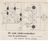
I came up with this concept for a power stage, using pentodes.
The idea is to get maximum power from two pentodes, and keep the feedback only in the output stage, while keeping distortion down. As I read here, partial feedback output stages are best driven by high output impedance driver stages.
-Anode to grid feedback
-Balanced feedback from the output trannsformer
-Fixed biasing
G2 power is omitted for clarity. Possible options for feeding G2 are a properly stabilised power supply, or a plain simple resistor a-la RH84. Pleas comment on that too.

Opinions?
The idea is to get maximum power from two pentodes, and keep the feedback only in the output stage, while keeping distortion down. As I read here, partial feedback output stages are best driven by high output impedance driver stages.
-Anode to grid feedback
-Balanced feedback from the output trannsformer
-Fixed biasing
G2 power is omitted for clarity. Possible options for feeding G2 are a properly stabilised power supply, or a plain simple resistor a-la RH84. Pleas comment on that too.

Opinions?
Penthode + CFB (using secondary) is nothing new. Take a look at Sansui AU70 schematic. That will work for sure.
Anode to grid feedback - what is it for ???
Additionally, if you want to implement CFB (cathode feedback), its better to use separate tertiary winding instead of secondary.
Anode to grid feedback - what is it for ???
Additionally, if you want to implement CFB (cathode feedback), its better to use separate tertiary winding instead of secondary.
One of the advantages of NFB is to low the output impedance when properly used.
Cathode feedback is voltage-series feedback, and then it effectively reduces output impedance.
Anode to grid FB is current parallel, which increases output impedance, so since this point of view, they cancels out together or almost counteract.
The advantage in respect to lower the distortion continues to work of normal way.
Cathode feedback is voltage-series feedback, and then it effectively reduces output impedance.
Anode to grid FB is current parallel, which increases output impedance...
Are you sure about this?
Are you sure about this?
Are you sure you are alive or you are dreaming?
Audio Research did this cathode feedback scheme with the ST 70.
ARC ST70C3
The Tango XE-45-5 PP output transformer has a secondary tap for cathode feedback.
Feral Eye
ARC ST70C3
The Tango XE-45-5 PP output transformer has a secondary tap for cathode feedback.
Feral Eye
Are you sure you are alive or you are dreaming?
It's a PP variant of the RH topology, there is local negative voltage feedback from output tube plate to grid based on the ratio of the rp of the preceding stage and the plate to grid feedback resistor. It does lower rp in the output tube significantly depending on how much feedback is employed.
Not always what you say is true. There are 4 elementary kinds of feedback:It's a PP variant of the RH topology, there is local negative voltage feedback from output tube plate to grid based on the ratio of the rp of the preceding stage and the plate to grid feedback resistor. It does lower rp in the output tube significantly depending on how much feedback is employed.
1) Voltage series: this is a when beta (The feedback ratio) senses voltage at output and feeds back voltage. This way input impedance is boosted, and output impedance is lowered (The most common form is a noninverting op amp with 2 feedback resistors);
2) Voltage parallel: beta senses voltage, and feedback current, input and output resistance are lowered;
3) Current series, both the output and input impedances are boosted (Triode with Rk without caps, also used in chips for vertical deflection in CRT displays);
4) Current parallel, which current in the output is sensed, and feedback as a current in the input, output impedance is boosted, and input is lowered (It makes a better current controlled current generator).
As a difference with other thread which I demonstrated my words, I will not do it here because in any textbook can be found such as demonstrations.
In some circumstances, topology of feedback can be mixed and it includes positive feedback, in the Seely´s book it is said that sometimes an amplifier can have a mix of positive current feedback and negative voltage feedback in order to obtain zero or negative output impedance.
Sorry if my English is not too good, but I believe you can understand me.
Cordially Osvaldo.
Last edited:
can Ultra-Linear and a cathode feedback output transformer winding be implemented in one output stage?
Yes, you will get benefits of both, actually I did it in 2 push-pull amps.
For details you can look for a book written by Menno van der Veen (I recommend last edition).
- Status
- This old topic is closed. If you want to reopen this topic, contact a moderator using the "Report Post" button.
- Home
- Amplifiers
- Tubes / Valves
- Double feedback pentode Power Stage
