I did. I didn't have room for big MKP's, but I bypassed the 470uF 'lytics with some nice MKP.
A good transformer coupled amp still sounds better to me but is also in a very different league money-wise...
PS. On the topic of output caps... my other OTL amp used Siemens MKV caps... those need quite long to burn in but then are really good.
It says 220 uF on both OPCap and cathode decoupling on your schema. Maybe you changed that?
No, the power transformer core should always be grounded.
I usually put some isolation, like cork, thin rubber or gasket material between the chassies and tranny, especially if magnetic chassie (steel). It isolates the magnetic flux to spread to the chassie and make it part of the core. That is to avoid ground currents in the audio ground circuits to induct by the chassie fluxing. Then I use a thick copper wire from tranny core to chassie ground lug. It can also isolate some vibrations. Use brass or other non magnetic bolts or isolating spacers.
Dielectric hysteresis of the electrolytic capacitor is very serious, and therefore does not recommend the use of electrolytic capacitor coupled output, the WCF output of the machine I done, thin film capacitors using 2.2uf can have a good effect, I recently bought a RIFA PHE426 3.9UF 400V thin film capacitor. In the final analysis is the key of low enough you with a high impedance load, if it is paired with a low impedance load recommend the use of low resistance pipe, for example, I use the 12AU7, if you use the 12BH7 effect will be better, also the output stage of the WCF tube suggested adding a cathode capacitance, but also can reduce the output impedance.
I English is not good, Chinese attached for reference only
电解电容的电介质迟滞是很严重的,因此不建议使用电解电容进行耦合输出,这类WCF输出的机器我做过,使用2.2uf的薄膜电容就可以有不错的效果,我最近又购入了RIFA PHE426 3.9UF 400V的薄膜电容。归根结底低频是否足够的关键是你搭配多高阻抗的负载,如果是搭配低阻抗负载建议使用内阻较低的管子,比如我用的是12AU7,如果你使用12BH7效果会更好,另外WCF输出级下管建议增加一个阴极电容,也能降低输出阻抗。


I English is not good, Chinese attached for reference only
电解电容的电介质迟滞是很严重的,因此不建议使用电解电容进行耦合输出,这类WCF输出的机器我做过,使用2.2uf的薄膜电容就可以有不错的效果,我最近又购入了RIFA PHE426 3.9UF 400V的薄膜电容。归根结底低频是否足够的关键是你搭配多高阻抗的负载,如果是搭配低阻抗负载建议使用内阻较低的管子,比如我用的是12AU7,如果你使用12BH7效果会更好,另外WCF输出级下管建议增加一个阴极电容,也能降低输出阻抗。


My guess is that most of the verdicts on the sound of this amp will be verdicts of the output caps. Anyone tried with big MKP or bypassing HQ lytics?
I tried electrolytic with bypass. After I tried with Claricaps, Solen, mundorf full film. The sound pretty much stays the same smooth & relaxing. The same setup preformed a little better with 1uf caps directly to non-headphone system. I believe the setup will suit someone searching this type of sound which is very nice in many aspects.
You are right Stajo... this was off the top of my head.
Built the amp in 2007 and have it sold long time ago. And I didn't say it sounded bad...
it was a very pleasant performer, but compared to other amps pleasant is not enough.
For Headset amplifier for DC coupling is the best choice, so some of the KG SEPP framework Headset amplifier circuit is the most worthy of consideration, using the positive and negative frame of dual power supply can realize the output of OCL, but for PRE-AMP it seems it is not very suitable for.
Baidu Fanyi is too awkward, but I English level is limited, only will look, with Chinese
对于耳机放大器来说DC耦合才是最好的选择,因此KG提出的一些SEPP构架的耳机放大器线路是最值得考虑的,使用正负双电源的构架可以实现OCL输出,但对于PRE-AMP来说似乎就不是很适合
Good lesson learned.
I learned that lesson myself
Great progress. Post some images when you have it making music!
Is there a good way to discharge all the caps at once or do I need to do each one? I will need to clean the wiring up after I prove the amp functions properly.
In the PSU? Put a bleeder. A resistor between plus and ground somewhere between the caps in the linear chain of RC/LC, closest to the biggest cap usually. If say you want to bleed 1mA, use ohms law.R=U/I=250V / 0,001 = 250 k. For power dimensioning of bleeder P=U*I=250 V * 0,001 = 0,25 W. Use 1 W for margin. It would take around 110 seconds for it to have gone down to 10 V left in 440 uF caps. If you want it quicker, lower resistor value. Remember to calculate, and that it steals your voltage (loads the trafo).
Last edited:
What is a safe voltage? I bleed the cap Dow but it keeps charging back to about .7 volts.
The voltage from the psu going into the audio circuit is supposed to be 250v. I am now getting about 300v. I Suppose I need to add a resistor.
What are your caps rated for? Yea they charge back a little after quick emptying. 0,7 volts you wont feel at this amps. Are your circuit conducting? Measure Vdrop over serial resistor in PSU.
Last edited:
Can you divide voltage using that R3 27K 2W resistor?
From 340V to 250V.
Any pros and cons?
Hello folks.
I recently joined you in building an optimized version with feedback. Tubes used, are ex-Soviet 6N23P.
Followed the schematic provided here, with some minimal modifications.
Changed 22kΩ output resistor to ground to a 2200Ω one, in order to minimise pop when inserting my 50Ω cans.
Also bypassed all electrolytic with ex-Soviet paper in oil & polystyrene film.
A nice 'fix', especially for those worried about using electrolytics in the signal path of any OTL.
When in parallel with good ol' PIO & film caps, there is no loss in transparency due to electrolytics.
Quite on the contrary, they blend perfectly together.
To the point that I sometimes use bypassed electrolytics even if I could avoid them (i.e. in positions where value needed isn't more than 10uF).
But, I digress.
Power supply wise, i used an indirectly heated 6C4P-EV valve rectifier, followed by R-C filter stages.
Heaters are all AC-lit with an artificial center tap and eleveted at around 50VDC. The amp is dead-silent.
The end result exceeded my expectations.
This little amp sounds very good, in my opinion.
Better than several previous builds of mine.
For example, it's more detailed and dynamic than Tortello's Zen-like solid-state.
And better articulated than my valve-rectified 6922 + 6080 OTL.
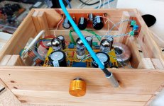
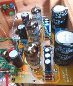
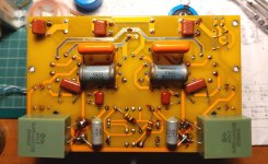
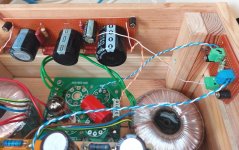
Some pictures:

I used this IKEA box until i find something better to put it in.

PCB top side

PCB under side

PSU section
I recently joined you in building an optimized version with feedback. Tubes used, are ex-Soviet 6N23P.
Followed the schematic provided here, with some minimal modifications.
Changed 22kΩ output resistor to ground to a 2200Ω one, in order to minimise pop when inserting my 50Ω cans.
Also bypassed all electrolytic with ex-Soviet paper in oil & polystyrene film.
A nice 'fix', especially for those worried about using electrolytics in the signal path of any OTL.
When in parallel with good ol' PIO & film caps, there is no loss in transparency due to electrolytics.
Quite on the contrary, they blend perfectly together.
To the point that I sometimes use bypassed electrolytics even if I could avoid them (i.e. in positions where value needed isn't more than 10uF).
But, I digress.
Power supply wise, i used an indirectly heated 6C4P-EV valve rectifier, followed by R-C filter stages.
Heaters are all AC-lit with an artificial center tap and eleveted at around 50VDC. The amp is dead-silent.
The end result exceeded my expectations.
This little amp sounds very good, in my opinion.
Better than several previous builds of mine.
For example, it's more detailed and dynamic than Tortello's Zen-like solid-state.
And better articulated than my valve-rectified 6922 + 6080 OTL.
Some pictures:

I used this IKEA box until i find something better to put it in.

PCB top side

PCB under side

PSU section
- Home
- Amplifiers
- Tubes / Valves
- The Morgan Jones mini tube headphone Amplifier
