Hi, sorry for posting this if it has been already answered elsewhere, but was not able to find straight answer in this forum.
I have a SE amp with floating OPT (secondary not grounded); this is technique recommended by Lundahl to overcome a HF roll off due to capacitive coupling between OPT primary and secondary, especially common to high impedance primary OPT's; I am using Lundahl LL1691B, 20K:8ohm.
I got a scope and would like to use it to measure a frequency response and actually compare grounded to floating OPT, but am not sure about correct way to take the measurements.
Since I do not have differential probes, if I take a measurement across the speaker terminals I will be effectively grounding the transformer trough the ground clip on the probe.
I could float my amp power supply when doing the measurement (disconnect PS from the amp chassis ground) and use battery powered (not grounded) signal generator; would that give me same result across the secondary as if secondary is floating (since in this case primary would be floating in respect to secondary)?
Other popular option would be to float the scope (disconnect the ground); of course, keeping in mind ungrounded scope could be very dangerous!; and measure across the OPT secondary. Here I am wondering about the effect of internal scope capacitance that could influence HF response?
Is there a correct way to measure floating OPT using regular scope without differential probes?
Why are you using such a high ratio?
Seems unusual, and to imply a very high B+??
Anyhow, I would simply use a small isolation transformer to "float" the scope. No third wire ground. (this is useful in the USA and North America where there is a 120v - neutral - ground "three wire" AC mains set up).
My scope is always isolated, because I don't want to put the ground lead inside a chassis and have the magic smoke exit.
Otoh, the sig generator, and other stuff is grounded unless I intentionally plug it into the isolated AC xfmr feed.
The sig generator you are using is connected to the input, so that shouldn't matter unless ur trying to float everything...
The scope represents a very high impedance so it should not load the output.
Btw, merely lifting the ground pin *may not* be sufficient to lift the scope's chassis above ground.
_-_-bear
Since I do not have differential probes, if I take a measurement across the speaker terminals I will be effectively grounding the transformer trough the ground clip on the probe.
Is there a correct way to measure floating OPT using regular scope without differential probes?
Yes, if you have a dual trace scope and A-B mode (or A+B with B inverted). Easier than floating the whole scope
") .
.Jaz
Agreed. Found a good post by Miles on another forum:
"It's necessary to ground one side of the secondary to provide a voltage reference for gNFB. If you don't, then there is no reference between the gNFB summing node and AC ground.
It's also a safety precaution. If the secondary is left floating, and there is a short circuit between the primary of the OPT and the secondary (let's say you forgot to connect the speeks and cranked it to 11 when you didn't hear anything. The resulting inductive kick back could cause the insulation between the primary and secondary to fail) a floating secondary becomes several hundred volts hot. That won't affect the operation, and you may not find out about it for years. That is, until you come into contact between a hot speaker while touching something grounded and get a really nasty surprise. If the secondary is grounded, then a primary-to-secondary short circuit blows the fuse. (You do fuse the primary side of your PTX, right?) That is also why it's a really bad idea to solve the problem of a three pin plug and a two slot socket with a pair of dykes to snip off the third wire safety ground. Or to build any VT equipment that doesn't have a third wire safety, and let's not even consider a design that doesn't have a PTX and runs directly off the AC mains. They didn't call such equipment "suicide boxes" for nothing.
If you float the secondary, it's essential to make certain that you can't contact a potentially hot contact, such as the speaker binding posts. VT equipment (and some solid state as well) operate at potentially lethal voltages. You want to keep those voltages where they belong, and not on the chassis, volume controls, tone controls, or anything else you might touch while the amp is working."
Adding speaker leads and a speaker to the secondary will add capacitive coupling to ground, as will attaching even an isolated scope. Big lumps of metal have capacitance as the rest of the universe acts as the second capacitor plate (and the Earth is much nearer than most of the rest of the universe).
Hi, thanks to all for your comments; I agree that I would also feel better to have OPT secondary grounded; and yes, of course, my chassis is grounded and there is a fuse on the power transformer primary.
It is interesting that this method of not grounding the secondary of OPT is actually coming up a lot, especially with this high impedance transformers.
On some of the specs for frequency response Lundahl actually puts a note “secondary winding not grounded”; apparently this clearly improves HF response.
Other schematics using same or similar OPT spec a high value resistor (ex. 33K) from secondary to ground; see attached.
The fact is that Lundahl OPT seems to be built extremely well, with 4K insulation spec between primary and secondary.
For those reasons I really wanted to measure frequency response to see the actual difference as would prefer to have secondary grounded as long as my HF does not suffer too much.
Considering post of DF96, it is probably the case that even if I do float the scope to take the measurements for flouting vs. grounded secondary actual scope mass would still add capacitive coupling to ground and not show actual “floating” situation, especially at HF where I am looking to find difference.
I will try a suggestion from Jaz and measure response at both speaker terminals relative to ground and then subtract one from each other.
What is the general opinion when taking Amp measurements; should the scope probe ground clip be connected to PS/signal star ground or to the chassis ground?
I got a 5ohm resistor between PS/signal ground to chassis/safety earth wire attachment.
Attachments
Floating the scope (on an isolation transformer, or using its internal isolation if so equipped) isn't a great idea because, face it, if it worked in the first place, we wouldn't be having this discussion: you already stated your OPT is "isolated"! We need something even more isolated-ier. A hunky power transformer isn't going to do much better than the OPT already (to be fair, it might, because a bank-wound type has lower capacitance than an interleaved shell-type OPT -- but the thing is, we don't *know* by how much).
Now, the problem is, the common mode current isn't very high (it's coming from a ~kohms primary, over maybe a few hundred pF), so it'll take a ridiculous inductance to "float" the measurement with a common mode filter. Even a pile of coax cable, threaded through high permeability toroids, will only net you an impedance in the kohms in the tens of kHz range. If the current is coming from the primary winding, its impedance will be on the order of kohms, so you need an impedance of 10s of kohms or higher.
The differential measurement using probes is handy (a 10Mohm, couple pF probe is hard to beat!), but only within the common mode range of your oscilloscope -- if the voltage turns out to be the full ~hundreds at the plates, you'll have a hard time viewing the couple of volts for the test, in lieu of a proper diff probe. Obviously, this depends on the OPT ratio. A nice low impedance OPT, maybe on a quad sweep amp or something like that, might be a piece of cake; a 20kohm OPT on a high voltage SET will have worse luck.
But all is not lost. You could take a very small transformer, which definitely has less capacitance than the OPT -- and which can be characterized -- and use that to couple the secondary voltage to your scope. It can even be some random ferrite transformer, as long as the inductance is enough for the end of the spectrum you'll be testing -- over 10kHz needs only 1mH, which is easily under a hundred turns, even on a small core. If you don't mind the turns ratio, you could easily use a transformer pulled from a switching power supply: the primary, which has to handle 300V in its intended application, will do a fine job with a few volts at relatively low frequencies.
Even more abstract methods could be used. For starters, you can measure the common-mode voltage simply by measuring the OPT secondary voltage to ground. This will be very susceptible to 60Hz hum (especially if hands are in proximity), but might still be a useful measurement.
You might infer the effect of grounding by measuring the current over a resistor to ground, or by creating a capacitance divider between OPT capacitance and a capacitor to ground. By varying the shunt capacitance, you can observe how the peaks change at the point of connection.
If you have an open OPT construction, you can try threading a turn through the core and measuring the induced voltage that way. This will give you a relative measure of frequency response, while doing a sweep or FFT or whatever, if not the actual gain. This is like having a separate feedback winding, which was sometimes done.
Tim
Thanks Tim, this ware really interesting suggestions!
Yes, differential measurement was hard to really do precise as AC voltage to ground on "non-grounded" OPT secondary ware over 200Vpp, so trying to measure difference across the secondary at various frequency proved to be difficult.
I tried method you suggested using additional transformer; I had small speaker impedance matching 8ohm:1.2ohm transformer which I connected across the OPT, in parallel with my "dummy" load, and then took measurements across the small transformer secondary. Here it was interesting that I got same -1db (at 13K) and -3db (at 19K) points whether OPT secondary was grounded or not!
This was surprising as measured capacitance between OPT primary and secondary is high at 7400pF, so grounding secondary should show faster HF roll-off.
I will do acoustical measurement using actual speaker and microphone with good HF extension and compare result of grounded vs. not grounded secondary; this should show the real effect at least in relative response.
Will report my findings once I get this done.
If the capacitance of the scope when isolated significantly effects the HF response of the "8ohm" secondary that is "floating", you'd best forget about whatever that response appears to be, because in the real world it just doesn't exist.
No doubt that differential active probes will have the least loading, but this is a low Z circuit and we're not measuring up to RF frequencies... so I'm of the view that the iso tranny works fine for this.
rrrs, you won't be likely to see the effect of the grounded vs ungrounded by measuring a speaker, because the frequencies effected are above 20Khz generally speaking.
_-_-bear
The fact is that with my OPT measured 7400pF primary to secondary capacitance you effectively get at 15Khz a 1.4K resistance from nominal 20K primary to ground; in case secondary is grounded!
I expect this to influence response below 20Khz as the load on the plate of the output tube would be reduced a lot; at 20Khz it would fall below 1K compared to nominal 20K!
Anyway, will give it a try and report if I find a difference.
I expect this to influence response below 20Khz as the load on the plate of the output tube would be reduced a lot; at 20Khz it would fall below 1K compared to nominal 20K!
Anyway, will give it a try and report if I find a difference.
I'll be very interested to see what the acoustic measurement shows. That big capacitance between the windings should really drain off the HF, but measuring should tell you.
Also the trick of a large resistance from one side of the secondary to ground and measure the current thru it should tell you a lot. Let us know what you find.
Also the trick of a large resistance from one side of the secondary to ground and measure the current thru it should tell you a lot. Let us know what you find.
Hi, will do acoustic measurements once I get new soundcard; managed to fry input on my one when trying to measure frequency response of the Amp and was lazy to build a input protection circuit....
Might take me few weeks to get it done, but will report what I find out!
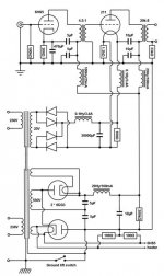
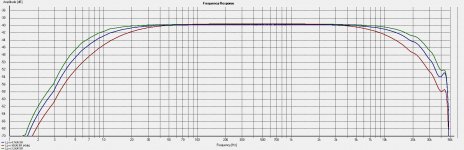
I did measure the frequency response of my OPT, just using my soundcard output/input, but obviously was not able to do a floating measurement as secondary gets grounded that way through the soundcard; you will see a small peak at 40+K.
You will see 3 different measurements using 3.2K, 4.7K and 10K as a primary load, all into 6.5 ohm on secondary.
4.7K is close to plate resistance of 211 tubes I am using.
Might take me few weeks to get it done, but will report what I find out!
I did measure the frequency response of my OPT, just using my soundcard output/input, but obviously was not able to do a floating measurement as secondary gets grounded that way through the soundcard; you will see a small peak at 40+K.
You will see 3 different measurements using 3.2K, 4.7K and 10K as a primary load, all into 6.5 ohm on secondary.
4.7K is close to plate resistance of 211 tubes I am using.
Attachments
Hi, Pano's suggestion of measuring AC voltage drop/current trough resistor connected between secondary and ground was really interesting; I used 27K from secondary to ground and got:
100Hz – 3.5Vpp
500Hz – 15.2Vpp
1KHz – 22.5Vpp
10KHz – 23.9Vpp
15KHz – 19.7Vpp
20KHz – 15.7Vpp
So, there is definitely capacitive coupling dependant on frequency; developing approximately 0.3mA current across 27K resistor at 1KHz, while there is hardly any current al low frequency.
Not sure how to interpret this data, but will do also a acoustical measurement once my sound card is fixed and report if I can find any measurable frequency response difference between grounded OPT, floating OPT and OPT connected to ground trough large resistor.
Interesting. Definitely some coupling there, but the 27K resistor really pulls down the voltage from the ~200Vpp you were seeing before. Pulls it down into a safer area.
Am I calculating right that the leakage impedance is about 200K?
As the 27K to ground is pulling less than 0.02W, you could likely load it harder.
Am I calculating right that the leakage impedance is about 200K?
As the 27K to ground is pulling less than 0.02W, you could likely load it harder.
So, I did finally get around measuring acoustic response and there is a difference; small but clear to see. At 20kHZ there is approximately 1.5db more roll-off with OPT secondary grounded vs. not grounded. I did re-measure few times and kept getting same result; so would say it is reliable; unfortunately forgot to measure with large resistor to ground, but would expect to be similar response as not grounded.
- Status
- This old topic is closed. If you want to reopen this topic, contact a moderator using the "Report Post" button.
- Home
- Amplifiers
- Tubes / Valves
- Floating OPT oscilloscope measuraments